What Is Structural Analysis in Engineering? Comprehensive Guide
Structural analysis is the engineering discipline that predicts how structures respond to applied loads. It ensures structures remain stable and serviceable throughout their design life. Applications range from skyscrapers and bridges to tunnels and mechanical systems such as vehicles.
This crucial engineering discipline provides the quantitative basis for understanding whether structures can carry their loads without excessive deformation or failure.
The question at the heart of structural analysis is straightforward. Given a structure and a set of loads, what are the resulting internal forces, stresses, and displacements? The answer determines whether a design is adequate or needs revision. Structural analysis is the primary tool engineers use to prevent failure. It underpins every design decision, from preliminary sizing to final checks.
The engineering of structures has evolved:
- Early structures relied on empirical rules and the intuition built from experience. Early “engineers” worked with masonry arches and timber frames.
- Modern structures are geometrically complex systems. They use a wide range of materials and are subject to demanding, often dynamic loading conditions. Meeting these challenges has driven the development of sophisticated analytical methods.
This article covers the core concepts of structural analysis, with a focus on advanced computational tools:
- The Finite Element approach is part of CAE (Computer-Aided Engineering). CAE is the use of software to simulate and analyze engineering designs.
- Recent developments in Artificial Intelligence and Deep Learning have enabled rapid exploration of design spaces. Attention will also be given to AI applications in Civil Engineering, where these methods have an impact.
A learning roadmap and key takeaways are provided at the end of the guide to help you structure your study path and quickly review the most important concepts, whether you are a student building foundational knowledge or a practicing engineer looking to incorporate modern AI-assisted workflows.
What is Structural Analysis?
Structural analysis examines how structures behave under loads.
- A structure is a system of interconnected elements.
- Elements in the structural model are designed to carry, transfer, and resist loads safely to the ground while maintaining their shape and stability.
The Eiffel Tower is a piece of structural engineering and art where the elements are visible:
- lattice truss members (diagonals and verticals) carrying axial forces,
- primary legs acting as inclined columns,
- horizontal girders distributing structural loads, and
- bracing systems providing stability against wind through triangulation.

Loads include external forces acting on the structure, temperature changes, and other environmental factors. These conditions can lead to deformation, vibration, and user discomfort. In extreme cases, structural failure can happen.
Tasks of structural analysis engineers:
- ensure structural integrity: no failure (yielding, buckling, fatigue)
- ensure structural performance: acceptable displacements, vibrations, and durability
- verify the structure under all relevant load cases and combinations
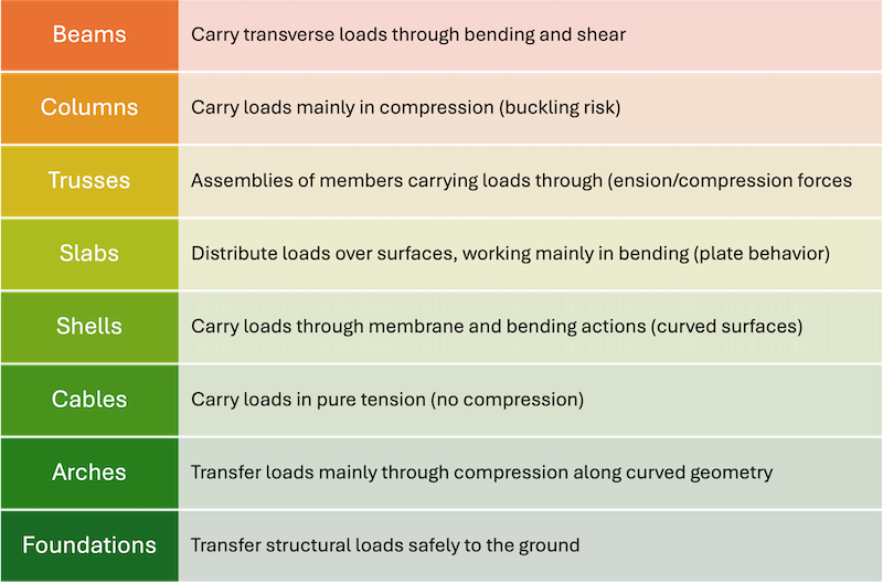
What are Structural Elements?
Structural elements are the individual components of a structure. Their function is to resist and transfer loads, each with a defined mechanical role.
A complete structural analysis combines these elements to represent the route along which forces travel from their point of application to the foundations (load path), e.g., from arches to columns, and ultimately to the foundations.
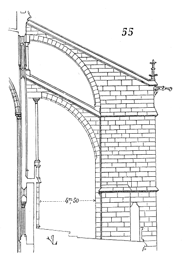
In a masonry arch (see figure), structural stability depends on keeping the line of thrust within the arch thickness.
Vertical loads are redirected into pure compression along this line, while horizontal thrust is generated at the supports and must be resisted by the abutments

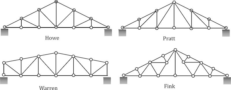
2D Modeling
Structural engineers sketch elements such as trusses in 2D (see figure). Engineers sketch elements before moving to 3D modeling. A 2D sketch captures the essential geometry (member layout, joint positions, and support conditions), without the complexity of a full 3D model.
Thus, the 2D approach is a fast, low-cost way to test configurations, spot problems early, and communicate intent clearly before committing to detailed design work.
What are Structural Components?
A structural component is a larger assembly than a structural element.
It is composed of one or more elements, including connections and secondary parts (e.g., a truss panel, a framed wall, a floor system). Components have more complex geometries and functions.
The entire structure is composed of these components, arranged to transfer loads to the ground safely.
In civil engineering projects, typical structural components include floor systems, roof trusses, bridge spans, and framed walls. Each combines multiple elements to perform its intended structural role.
Typical Loads (Examples)
Typical examples of the loads in the civil sector include:
- wind acting on skyscrapers
- snow accumulation on roofs
- seismic loads from earthquakes
- dynamic loads on bridges
Typical examples of the loads in other engineering sectors include:
- inertial loads due to acceleration (automotive, aerospace)
- thermal loads from temperature gradients (turbines, engines, electronics)
- pressure loads from fluids (pipes, pressure vessels, hydraulic systems)
A reference textbook for Aerospace structural mechanics is Introduction to Aerospace Structures and Materials (Alderliesten).
What are the Key Aspects of Structural Analysis?
Structural analysis focuses on quantifying structural response, detecting risks, and ensuring safe, efficient design via modeling and verification.
What are the Basic Principles of Structural Mechanics?
Structural mechanics is governed by three fundamental principles: equilibrium, compatibility, and material behavior.
These principles are essential in structural analysis. They guide design decisions and the adaptation to new materials and techniques. They must always be satisfied simultaneously in any valid structural solution.
What is Equilibrium?
Equilibrium is a fundamental principle of structural mechanics that requires the sum of all forces and moments acting on a structure, or on any part of it, to equal zero.
- Sum of forces equals zero / Sum of moments equals zero
When the forces and moments acting on a structure are balanced, the structure does not accelerate or collapse.
Engineers calculate:
- External loads
- Support reactions
- Internal and external forces: Equilibrium requires balancing both to ensure structural stability.
- Internal forces such as axial/shear forces and bending moment
Without equilibrium, the solution is physically invalid.
External vs Internal Forces
- External forces are applied from outside the structure: loads (dead, live, wind, seismic), support reactions, and environmental effects.
- Internal forces develop inside the members to resist external loads. They include axial force (N), shear force (V), bending moment (M), and torsion (T).
Free-Body Diagrams
A Free-Body Diagram (FBD) isolates a part of the structure and shows all external forces and reactions acting on it. It is the essential first step in structural analysis.
To create an FBD:
- isolate the body, show all applied loads,
- replace supports with reactions, and label forces clearly
- apply the equilibrium equations: ΣF = 0 and ΣM = 0.
What is the Method of Sections?
The Method of Sections is a hand-calculation technique that isolates a portion of a structure to determine the internal forces at any chosen cross-section, using only the three equations of static equilibrium.
An imaginary cut is made through the structure, a free-body diagram is drawn for one side, and the axial, shear, and bending forces at the cut are solved directly. Mastering free-body diagrams and the method of sections allows engineers to move from external loads to the internal forces that members must resist.
"In almost every problem of structural mechanics, the basic analytical tool is the free-body diagram." Gere, J. M. (2004). Mechanics of Materials (6th ed.). Brooks Cole / Thomson Learning.
Compatibility
Compatibility involves coordinating deformations to maintain stability and prevent failure. Ensuring compatibility guarantees internal consistency, prevents distortions, and maintains the structure’s stability.
Connected elements must deform together, respecting geometry and constraints. In a continuous beam, spans share consistent rotations and deflections.
Ignoring this leads to incorrect stress distribution.
Material Behavior
Material behavior defines how stress translates into strain.
Important considerations:
- Linear elasticity versus nonlinear response
- Plastic deformation and failure
- Time-dependent effects such as creep and fatigue
Accurate material models are essential for realistic structural predictions. Understanding material behavior is not merely a prerequisite but an art form within structural mechanics.
A reference text for civil engineers, useful for understanding material behavior, is Timoshenko, S. P., & Gere, J. M. (1972). Mechanics of Materials. New York: Van Nostrand Reinhold Company.
What is the Role of Simulation?
The role of simulation is to solve the equations governing structural behavior at scales and levels of complexity that no hand calculation can achieve.
Structural analysis is fundamentally predictive: it uses physical models to estimate how a structure will respond before it is built.
These models describe structural behavior using equations. Equations govern equilibrium, compatibility, and material laws. They range from simple algebraic forms to differential equations. The core challenge is solving these equations for real structures.
- In practice, structural analysis relies on simulation software that implements and solves physics-based models using numerical methods, such as finite element analysis (FEA).
- A recent extension is the integration of data-driven approaches (AI), in which physics-based simulations generate data or constraints to improve learning and prediction.
To learn about the latest advancements in AI for design engineers, read how AI can transform engineering design.
In practice, the value of a structural simulation is only as high as the fidelity of its inputs. Experienced engineers understand that mesh quality, boundary condition assumptions, and material constitutive models are the foundation. A safety factor extracted from a poorly constrained FEM model becomes a risk.
"All models are wrong, but some are useful." — George E. P. Box, statistician and engineer
- The role of FEM: Finite Element Analysis (FEA), or Finite Element Method (FEM), is the standard CAE approach for structural analysis. FEM can include various assumptions on the structural behavior to be modeled: static, dynamic, linear, and nonlinear approaches are possible.
- A comprehensive structural analysis solution involves CAD and FEM simulations, along with advanced modeling techniques, to evaluate critical performance metrics, including
- global stiffness,
- maximum displacement,
- minimum safety factor,
- first natural frequency.
References:
- Box, G. E. P., & Draper, N. R. (1987). Empirical Model-Building and Response Surfaces. Wiley. (source of the cited quote)
- NAFEMS. (2022). Best Practice Guidelines for Structural Simulation. National Agency for Finite Element Methods and Standards.
What is the Role of BIM?
BIM, or Building Information Modeling, is a methodology in which a shared 3D model contains data beyond geometry, e.g., materials, sections, load-bearing roles, and construction sequence positions, accessible to all disciplines.
In other words,
"BIM is not a software. It is a process that, when properly implemented, gives every member of a project team access to the right information at the right time." Chuck Eastman, BIM Handbook: A Guide to Building Information Modeling (Wiley, 2011)
For structural engineers, BIM is the natural starting point for FEM. Rather than rebuilding geometry and member properties from scratch inside a simulation environment, engineers transfer them directly from the BIM model into the FEA solver.
- BIM examples include platforms like Autodesk Revit, Tekla Structures, and Bentley OpenBuildings.
- The standard transfer format is IFC (Industry Foundation Classes), an open schema that carries geometry, element types, and material data across platforms.
- Proprietary links also exist: Revit to ROBOT Structural Analysis, Revit to SAP2000, and Tekla Structures to STAAD.Pro are common in civil and structural practice.
Caveats: The transfer is never clean. BIM models are built for coordination and documentation, not for analysis. Geometry must be simplified: architectural solids become structural centerlines, slabs become shell elements, and connections must be explicitly defined. This cleanup step, called model idealization, is where significant engineering judgment is applied before a single analysis runs.
See also: Autodesk BIM Building Information Modeling page.
Methods of Structural Analysis: Analytical Methods
Analytical methods use closed-form equations derived from mechanics. The moment distribution method is a classic analysis method for indeterminate structures. It is valued for its simplicity and ease of manual application to beams and frames.
Analytical methods are essential for:
- Simple structures
- Preliminary design
- Validation of numerical models
For indeterminate structures, advanced techniques such as virtual work and stiffness matrix analysis are often used to achieve accurate results.
Indeterminate structures or statically indeterminate structures more closely mimic real systems but require advanced analysis methods to account for their additional unknowns and ensure stability.
Statics of Structures
Static Analysis evaluates structures under constant loads, focusing on gravity loads. In statics, engineers compute:
- Support reactions
- Internal forces
- Basic deflections
Static loads are constant forces, such as self-weight, while dynamic loads act abruptly, such as wind or seismic activity (see next section).
Reference article about basics and applications for static structural analysis.
Dynamics of Structures
Dynamics addresses time-dependent behavior. Such a behavior is captured by the following standard 2nd-order differential equation, in matrix form:
[M]{ü} + [C]{u̇} + [K]{u} = {F(t)}
where the matrices [ ] and vectors { } are:
- [M] = Mass matrix (kg), [C] = Damping matrix (N·s/m), [K] = Stiffness matrix (N/m)
- {ü} = Acceleration vector (m/s²), {u̇} = Velocity vector (m/s), {u} = Displacement vector (m)
- {F(t)} = Time-varying external force vector (N) representing variable inputs
The equation is written in matrix form because real structures have many degrees of freedom (DOF).
Degrees of Freedom (DOFs):
- A DOF is an independent direction in which a point in a structure can move or rotate.
- A 3D model’s node has up to six DOFs:
- three translations (along x, y, z)
- three rotations (about x, y, z)
- Large models with thousands of nodes involve many coupled equations of motion.
Matrix form:
- Matrix notation expresses and solves equations simultaneously, showing how motion at one point affects others through off-diagonal terms of [K] and [M].
- Solving the equations finds the displacement vector {u(t)}. This indicates how each point moves over time.
- Engineers use this to determine quantities like inter-story drifts, accelerations, and stresses, which are then checked against code or performance limits.
Typical Applications of Dynamic Structural Analysis
Typical applications include:
- Earthquakes, where ground motion enters as an equivalent force vector {F(t)} = −[M]{1}·ü_g, with ü_g being the ground acceleration. The mass matrix influences seismic forces: heavier structures face larger forces, and their natural periods, determined by [M] and [K], dictate their response to ground motion.
- Wind loads, relevant for tall or slender structures, where fluctuating wind pressures generate a time-varying {F(t)} and damping [C] becomes critical to prevent excessive oscillations.
- Modal analysis is a technique that identifies a structure’s natural frequencies and mode shapes to predict its response to dynamic excitation. Time-history simulations are the standard methods for evaluating this behavior.
- Vibrations arising from machinery, traffic, or human activity, where the concern is often resonance: if the excitation frequency matches one of the structure’s natural frequencies, determined by [K] and [M] alone, response can grow dramatically.
Learn more about vibrations and how to predict and mitigate structural vibration effects.
Static vs. Dynamic Structural Analysis: Summary Table
Numerical Methods: Finite Element Analysis (FEM)
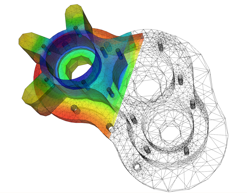
Analytical solutions to equations such as [K]{u} = {F} are limited to simple geometries. Real-world structures such as dams, aircraft wings, and bridges require numerical methods. FEM solves this by breaking complex domains into smaller, manageable pieces.
Discretization and Meshing
Discretization converts a continuous domain into a finite system suitable for computation. The result is the mesh.
- A node is a point where unknowns are computed. In structural problems, these are displacements u_x, u_y, u_z, and, when required, rotations.
- The set of variables at a node defines its degrees of freedom (DOF) and determines the size of the global system.
- An element is a small region defined by a set of nodes.
- Typical shapes are: triangles and quadrilaterals in 2D; tetrahedra and hexahedra in 3D.
- Within each element, the field is approximated using interpolation functions based on nodal values.
- The mesh is the collection of all elements and nodes covering the domain. Its definition controls both accuracy and computational cost.
- A coarse mesh reduces the number of DOFs and solution time. However, it cannot capture strong gradients.
- A fine mesh increases resolution and cost. The relevant quantity is not overall density but distribution.
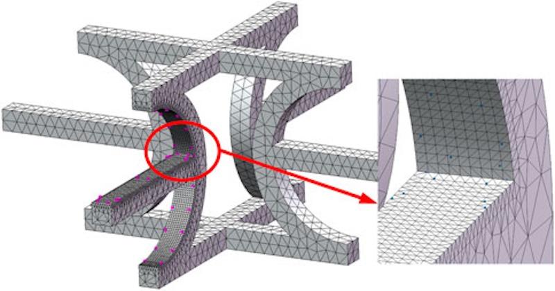
Mesh refinement is required in:
- stress concentrations = localized regions where stress rises sharply due to geometric features such as holes, fillets, or notches
- supports and constraints, where boundary conditions (constraints that define how a structure is fixed or loaded at its boundaries) are applied
- load application regions
Uniform regions with smooth variation can be modeled with larger elements. Mesh design is a modeling choice that directly impacts solution reliability.
Recommended Common Element Sizes for Typical Civil Engineering Components
The following are starting recommendations.
Make sure to always validate with a convergence study for your specific geometry, loads, and software (SAP2000, ETABS, STAAD, ANSYS, Abaqus, etc.).
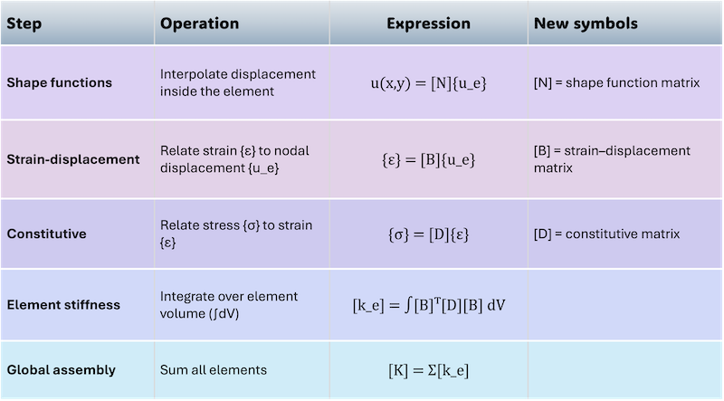
From Mesh to Matrix Equation (Linear Analysis)
From the mesh, the problem is written in algebraic form. Element-level relations connect nodal displacements to strains and stresses; integration then yields stiffness matrices.
Assembly of all elements produces the global system [K]{u} = {F}.
Solving it gives the displacement field over the entire mesh.
What are the Different FEM Approaches?
FEM structural analysis is divided into two primary approaches: Linear and Nonlinear.
- Linear Analysis, for small deformations within the elastic range
- Nonlinear Analysis, for complex behaviors involving large deformations, plasticity, or contact.
Selecting the correct approach is the single most consequential modeling decision an engineer makes. It determines both the accuracy of results and the computational resources required.
Summary of the FEM Process Step by Step
The Finite Element Method (FEM) is a numerical technique for analyzing structural behavior under various conditions by discretizing complex structures into smaller, more manageable elements. The process is:
- Discretization — The structure is divided into finite elements forming a mesh. Mesh quality directly affects accuracy.
- Element Modeling — Material properties, estimated loads, and boundary conditions are assigned.
- Element Interaction — Neighboring elements exchange forces and displacements.
- Assembly and Solution — A global system of equations is solved using matrix methods.
- Validation and Iteration — Results are checked and refined until convergence is reached.
Linear Analysis
A solid understanding of linear structural behavior is essential before progressing to complex nonlinear analysis, as it provides the foundation for accurately modeling and predicting nonlinear responses and potential structural failure. In short:
- Small deformations
- Linear material response
Linear Finite Element Analysis is used to analyze structures in which deformations remain small and material behavior follows Hooke’s Law: stress is directly proportional to strain within the elastic range of a material.
Nonlinear Analysis
Nonlinear Finite Element Analysis (NLFEA) addresses the limitations of linear modeling by accounting for large deformations, plastic behavior, and nonlinear boundary conditions. It captures three categories of complexity that linear analysis cannot:
- Material nonlinearity: plasticity, cracking, or crushing
- Geometric nonlinearity: large deformations that alter structural stiffness
- Contact problems: surfaces that interact, separate, or slide under load
In civil engineering, reinforced concrete structures require nonlinear material models, while slender or flexible structures demand geometric nonlinearity to produce safe, reliable predictions.
In Summary: Choosing the Right FEM Approach
The choice between linear and nonlinear FEM is not a matter of preference — the physics of the problem dictates it. Applying a linear model where nonlinear behavior governs will systematically underestimate risk.
Applied Finite Element Analysis
Simulation is where structural theory meets engineering practice. Applied FEA produces the quantitative evidence that determines whether a design is approved, modified, or rejected.
Applied Finite Element Analysis in Civil Engineering
Civil engineering structures operate at a scale where the consequences of analytical error are severe. FEM is the standard tool for evaluating the structural integrity of buildings, bridges, tunnels, and dams, each of which requires specific load cases, material models, and boundary conditions tailored to its physical context.
Civil Engineering Example: Dams
- Scenario: Interaction between structure, water, and soil
- Risk: Stability under varying hydrostatic and seismic loads

Civil Engineering Example: Tunnels
- Computation: Stress distribution in the surrounding ground mass
- Risk: Influence of excavation on adjacent structures and soil stability
A masonry arch tunnel illustrates one of the oldest and most resilient structures in civil engineering. The repeating arch geometry distributes compressive forces efficiently along the curved profile, a principle that predates FEM by centuries but is now routinely validated through it.

Civil Engineering Example: Bridges
- Issue: Fatigue and long-term material degradation
- Scenario: Load evolution over time under traffic, wind, and thermal cycles

Other Applications
FEA is widely applied to high-rise buildings, enabling engineers to simulate wind loads, seismic excitation, and variable occupancy patterns. These outputs directly inform design optimization and regulatory compliance.
Applied Finite Element Analysis in Various Industries
Structural integrity is a universal engineering requirement. FEA provides a consistent, physics-based framework for predicting performance and preventing failure across sectors where the materials, scales, and load conditions differ significantly.
Machinery Industry
- Reduce vibration and mechanical resonance in rotating equipment
- Improve the durability and lifespan of load-bearing components
- Apply advanced structural techniques for performance evaluation, reliability assessment, and design optimization
Aerospace Industry
- Analyze structures under extreme combined loads and temperature gradients
- Optimize structural weight without compromising safety margins
- Predict fatigue and failure modes for long-term mission reliability
Automotive Industry
- Conduct crash simulations to enhance occupant protection
- Perform fatigue analysis under repetitive and variable loading cycles
- Deploy high-performance computing to manage the complexity of full-vehicle models
Electronics Industry
- Perform thermal and structural stress analysis of circuit boards and components
- Predict deformation under mechanical loads or thermal cycling
- Improve long-term reliability and functional lifespan of electronic assemblies
The Engineering Imperative Behind Every Simulation
From a concrete dam retaining millions of cubic meters of water to a circuit board enduring thermal cycling, FEA serves a consistent purpose: surfacing failures before they occur and giving engineers the quantitative confidence to act on their designs.
"The engineer has been, and is, a maker of history." James Kip Finch, Engineering and Western Civilization (McGraw-Hill, 1951)
That history is now written in simulation before it is built in steel, concrete, or silicon. The breadth of FEA’s applications across civil, mechanical, aerospace, automotive, and electronics engineering reflects a straightforward reality: wherever a structure bears a load, rigorous analysis converts design intent into engineered certainty.
Structural Analysis Software: Quick Guideline
The following tables compare widely used FEA software packages across general engineering and civil engineering applications, covering their primary strengths and typical use cases.
General-Purpose Structural Analysis Software Comparison
Learn more about the recent applications and innovations in CAD technology.
Civil Engineering Structural Analysis Software Comparison
Structural Analysis in Practice
Structural analysis runs through every stage of an engineering project, from the first design decision to the final report. This section covers the engineer’s role, real-world case studies, results communication, emerging challenges, and the learning path for those building expertise in the field.
What is the Role of Structural Engineers?
The role of structural engineers is to ensure safety across all phases of a project. The civil engineering sector relies on structural engineers for safe and efficient design. Structural engineers are transitioning toward simulation-first and data-driven workflows.
Responsibilities include:
- Designing structural systems
- Selecting materials
- Performing analysis and validation
- Ensuring long-term reliability
- Designing and analyzing structural members such as beams, columns, and trusses
They increasingly rely on simulation tools and data-driven methods.
Case Studies and Worked Examples
Three practical civil engineering examples illustrate how structural analysis is applied in real projects.
These examples show the progression from basic equilibrium checks to full FEM models commonly used in building and infrastructure design.
The examples below are illustrative and use representative values, for educational purposes only!
- Example 1: Simply Supported Beam (Determinate). A 6 m concrete beam (300 × 500 mm) carries a uniform dead load of 15 kN/m and a 40 kN live point load at midspan.
- Hand calculation gives a maximum moment of 105 kNm and a deflection of 12 mm.
- FEM shell model confirms results within 1.5%.
- Example 2: Indeterminate Portal Frame. A single-story portal frame (4 m high columns, 8 m beam) with fixed bases resists a 25 kN horizontal wind load.
- The stiffness method yields a maximum joint moment = 52 kNm and a roof drift = 14 mm.
- FEM verification matches within 3%.
- Example 3: Reinforced Concrete Flat Slab. An 8 m × 8 m bay flat slab (200 mm thick) with drop panels supports 6 kPa dead + 4 kPa live load.
- FEM analysis shows a maximum negative moment at the columns of 142 kNm/m and a central deflection of 17 mm (span/470).
- A refined mesh near the columns was essential for an accurate punching shear check.
Reporting Results and Design Handover
Structural analysis does not end with a solved model.
Results must be translated into clear, actionable outputs.
Thus, non-specialist stakeholders (architects, contractors, and clients) can act.
Clear handover documentation reduces design iterations, prevents misinterpretation on site, and creates a traceable record for future inspections or modifications.
A well-structured report typically includes:
- Executive summary: governing load case, critical locations, and overall pass/fail status
- Key outputs: maximum displacement, peak stress or utilization ratio, and first natural frequency, where relevant
- Visual evidence: stress contour maps, deformed shapes, and bending moment diagrams annotated with critical values
- Design recommendations: required section changes, reinforcement adjustments, or areas flagged for further investigation
- Assumptions and limitations: model boundaries, material models used, and any simplifications that affect interpretation
For civil engineering projects, results are cross-referenced with the applicable code (e.g., Eurocode, ASCE 7). They are presented alongside the corresponding safety factors.
Where FEA is the primary method, a brief validation note confirming convergence, along with any hand-calculation checks, should accompany the output.
Further reading (see also section “Further Reading and Resources” ):
- Hibbeler’s Structural Analysis covers result interpretation for standard cases
- Bathe’s Finite Element Procedures addresses FEA output validation in depth.
- For code-compliant reporting, refer directly to Eurocode 0 (EN 1990) or ASCE 7.
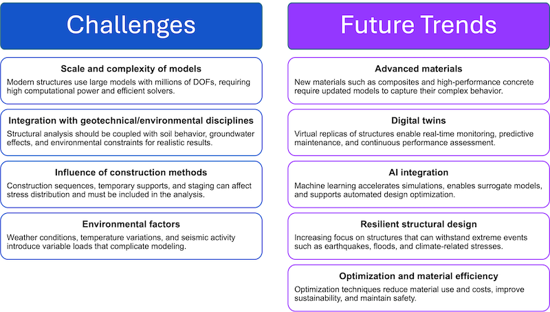
Challenges and Future Trends in Structural Analysis
Structural analysis is evolving rapidly as projects grow in complexity and performance requirements increase.
The table below summarizes the key challenges engineers face today alongside the major trends shaping the future of the discipline.
Learning Roadmap: How to Master Structural Analysis
Structural analysis builds progressively from basic principles to advanced computational methods. Follow this step-by-step roadmap to develop a strong intuition first, then scale to real-world tools and modern techniques.
Key Takeaways
- Structural analysis predicts structural response to loads.
- Applications span civil, aerospace, and automotive engineering.
- Core principles are equilibrium, compatibility, and material behavior.
- FEM is the primary tool for complex problems.
Further Reading and Resources
Textbooks
- Hibbeler, R.C.: Structural Analysis (undergraduate level for statics, indeterminate structures, and matrix methods)
- Bathe, K.J.: Finite Element Procedures (graduate-level FEM reference)
- Chopra, A.K.: Dynamics of Structures (seismic and dynamic analysis)
- Cook, R.D. et al.: Concepts and Applications of Finite Element Analysis (FEM with civil engineering focus)
Codes and Standards
- Eurocode 0–8 (EN 1990–1998): structural basis, actions, and material-specific design
- ASCE 7: Minimum Design Loads and Associated Criteria for Buildings and Other Structures
- ISO 2394: General Principles on Reliability for Structures
Software Documentation
- ANSYS, Abaqus, SAP2000, and ETABS each publish official verification manuals and theory guides. Consult these before benchmarking any model.
FAQs
Why are engineering principles important in construction, and how are they applied?
Engineering principles are indispensable in construction processes. They ensure that structures are safe, stable, and functional.
The main tool to apply these principles is structural analysis, which predicts how structures respond to loads and guides design decisions to prevent failure and optimize performance.
What are the current trends in monitoring and analysis of structural health?
Structural health monitoring in the built environment relies on sensors, IoT (Internet of Things) systems, and data analytics. Engineers collect real-time data to detect damage and assess performance. Digital twins and machine learning models help interpret this data.
What is the difference between static and dynamic structural analysis?
Static analysis evaluates structures under constant loads that do not vary with time. Dynamic analysis considers time-dependent effects such as earthquakes or vibrations. Dynamic problems require more advanced methods, such as time-history simulations, to capture inertia and damping effects.
What are the key differences between structural analysis and structural design?
Structural analysis typically determines how a structure behaves under loads. Structural design uses those results to define dimensions, materials, and reinforcement. Analysis answers what happens, while design determines what should be built to meet safety, cost, and performance requirements.
How does structural analysis differ for architects versus structural engineers?
Architects focus on spatial layout and aesthetics using simplified structural concepts. Structural engineers perform detailed calculations and simulations. Their deliverables include load calculations, reinforcement drawings, and technical specifications that ensure safety, compliance, and constructability.
What is involved in the concept of safety?
Safety in structural analysis involves comparing predicted structural behavior against allowed material strengths and safety factors.
What are matrix methods in Structural Analysis?
Matrix methods are computational techniques for solving systems of linear equations and are used in computer programs. They organize equations systematically: each row represents an equilibrium condition at a node, and each column represents a node’s degree of freedom. The matrix coefficients show how a node’s movement affects connected forces.
What are the main advantages of matrix methods?
This matrix representation allows engineers to (1) handle large and complex structures with thousands of nodes efficiently; (2) apply boundary conditions and external loads systematically; and (3) use computers to perform calculations quickly and accurately, which would be impractical by hand.
What determines the accuracy of Finite Element Analysis?
The accuracy of FEA hinges on the iterative nature of the process. Engineers validate results by comparing them to theoretical expectations or experimental data. They are checking for convergence, mesh density, element type, boundary conditions, loads, and material properties. In the end, they ensure the computed behavior reliably predicts real-world responses.
What is the difference between linear and nonlinear Finite Element Analysis FEA?
Linear Finite Element Analysis is used to analyze structures in which deformations remain small, and materials follow Hooke’s Law. Nonlinear Finite Element Analysis (NLFEA) addresses limitations in linear modeling by accounting for large deformations, plastic behavior, and nonlinear boundary conditions. Nonlinear Analysis accounts for material nonlinearity and geometric changes during loading.
What is the collaboration between engineers and designers?
The relationship between structural analysis and design is iterative, requiring collaboration between engineers and designers throughout the project. Structural analysis informs design decisions by providing crucial information about how structures respond to various loads and forces. Thus, structural analysis allows architects to push design boundaries while maintaining structural integrity.
What is a forensic investigation?
Forensic investigation is the systematic examination of a structure following an incident to determine how and why it failed. In a structural engineering context, forensic investigation applies simulation and physical analysis to identify the root causes of collapse. It produces findings that inform legal proceedings, insurance assessments, and forensic investigations, using structural analysis to determine the causes of structural failures. Preemptively, this stresses that structural analysis is essential for compliance with building codes and regulations in civil engineering projects.