What is CAD Technology? Applications and Future Innovations
Computer-aided design (CAD) technology uses specialized software to create precise models of products on computer systems. Models carry real dimensions, so you can simulate how a part behaves under load, drive a machine tool from the same geometry, and resolve industrial design issues before anything is manufactured.
Computer-Aided Design (CAD) software produces two outputs that organizations rely on:
The first is geometry, which drives computer-aided manufacturing and simulation.
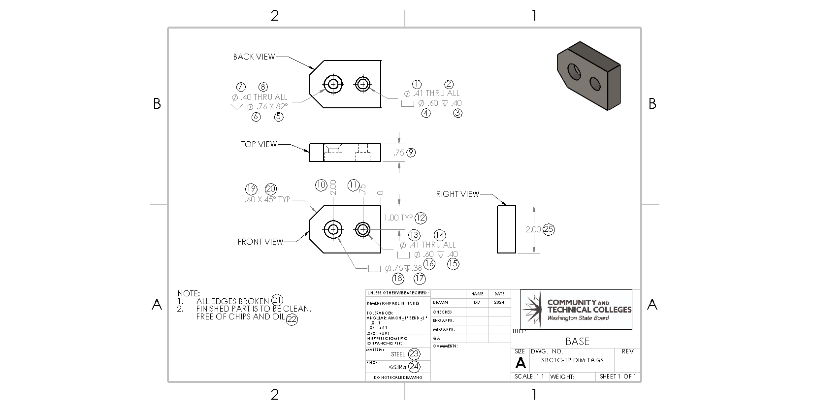
The second is technical documentation. A dimensioned drawing with its tolerance callouts is what a supplier quotes against, and the same model generates the technical illustrations in the service manual.
Key takeaways
Quick facts about CAD technology:
CAD creates precise 2D drawings and 3D models for design, simulation, manufacturing, and documentation.
Common model types include 2D drafting, 2.5D geometry, 3D solids, and NURBS surfaces.
STEP and IGES facilitate the exchange of CAD data between software systems.
Manufacturing cost depends on drawing tolerances, not just model precision.
For mechanical engineers, industrial designers who work in Computer-Aided Design (CAD) every day, and managers deciding which systems are worth the budget, the difference matters in precision, prototyping cost, collaboration, and how quickly teams can move from concept to production.
This article explains how CAD models are built, which file formats move design data between vendors, how the software evolved from a 1963 research prototype into the 2026 toolchain, which core features matter most, where different industries use CAD, what benefits and limitations come with it, and how machine learning is changing design evaluation and simulation.
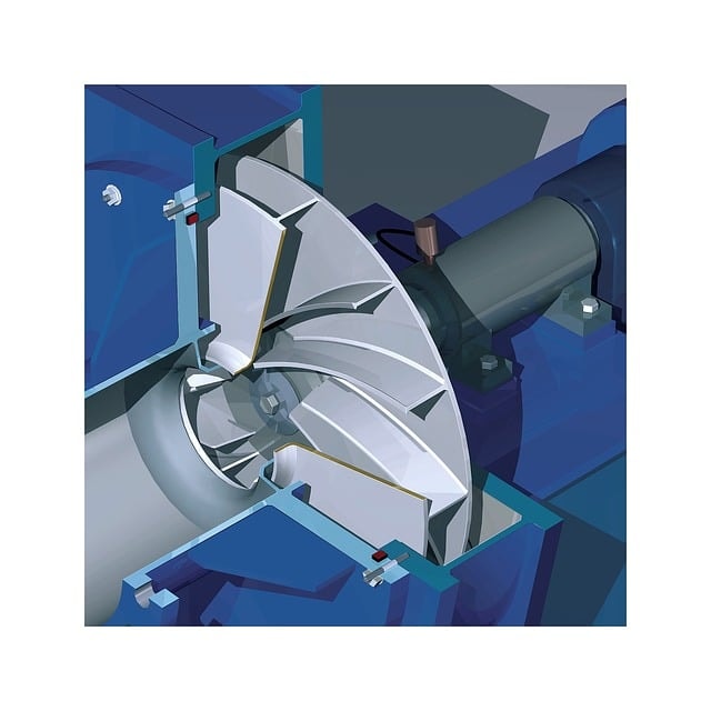
Table of contents
CAD technology: definitions and examples
Types of CAD models
Examples of CAD software
The evolution of CAD software
Key features of computer-aided design
Computer-aided design in the automotive industry
Applications of CAD technology in other industries
Benefits of CAD technology
Common challenges and limitations
What will the future of CAD technology be?
Conclusions
FAQ
Sources
CAD technology: definitions and examples
Computer-aided design and drafting, sometimes abbreviated CADD, rests on a geometry kernel: the code that represents a solid and answers questions about it, such as whether two bodies intersect and what volume remains when you subtract one from the other. CAD enables designers to create a digital replica of a physical object and reuse it downstream. CAD applications span industrial, product, and automotive design, as well as production engineering, and the same models feed R&D work, all of which depend on accurate geometric modeling of points, curves, surfaces, and solids.
CAD systems sit within the digital thread as the broader platform for managing versioned design data across downstream use cases. Their outputs are electronic files, so product data management systems can version them, and manufacturing equipment can consume them without a manual translation step.
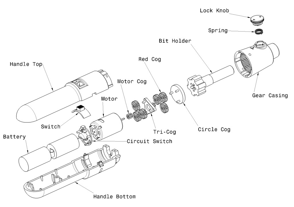
A component is a single part in a model.
An assembly is a collection of components forming a complete system. Assembly design adds mates and joints between components, so assembly modeling can detect interference and check clearances before any part is made of metal. Virtual assembly simulations validate build sequences before physical parts arrive.

CAD software uses constraint-based modeling to control and update designs based on defined geometric and dimensional relationships, such as alignment between two faces or a fixed angle between two edges. Ivan Sutherland's Sketchpad already solved geometric constraints in 1963, which is why the idea predates every commercial package on the market.
Interoperability rests on neutral standards. STEP, published by ISO as the ISO 10303 family, carries exact boundary-representation geometry across vendors, along with the assembly structure that holds the parts in place. IGES, the older specification, carries surfaces and curves.
| Format | Type | Carries | Loses | Use when |
|---|---|---|---|---|
| DWG | Autodesk proprietary, binary | Every AutoCAD feature, lossless inside the Autodesk ecosystem | Specification is unpublished, so other programs read it through reverse-engineered libraries | The work stays inside Autodesk tools |
| DXF | Autodesk documented, text-based, published since 1982 | 2D geometry readable by almost every CAD, CAM and CNC package | No 3D solid concept | Sending 2D profiles to a cutter |
| STEP (ISO 10303, AP242) | Neutral ISO standard | Exact boundary-representation solids, assembly structure, semantic PMI including GD&T and datums | The feature tree | Solid geometry crosses a vendor boundary |
| IGES | Neutral, frozen at version 5.3 in 1996 | Surfaces and curves | Watertight solids, assembly hierarchy, tolerancing | Only when the other end cannot accept STEP |
Types of CAD models
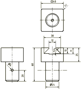
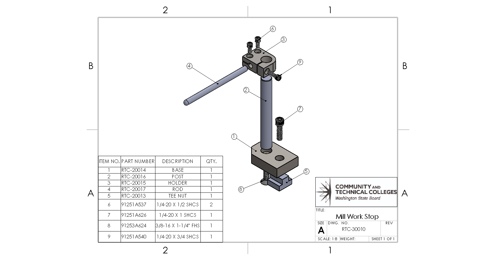
2D CAD uses lines and arcs to create precise drawings on a flat plane. It is used for plans and sections in architects' designs. Mechanical departments use it to create detailed technical drawings that carry every dimension and tolerance a supplier needs to quote the part.
2.5D CAD combines 2D and 3D features to describe complex shapes. The geometry is prismatic: it has real depth, and the depth varies across the part, though no feature overhangs another. Objects of this type are often stored as contour maps that give thickness at each point. The restriction has a practical payoff because a 2.5D part can be machined on a three-axis mill, and its toolpath generation remains computationally cheap, whereas optimal toolpaths for true 3D geometry are far more difficult to compute.
3D CAD represents a component or an entire system in three dimensions on a computer screen. As processing power and graphics capabilities improved, 3D became the default for mechanical work, and CAD programs can produce both 2D and 3D output to meet different design needs. You can section the model and check how two parts fit before either one exists.
Freeform and surface CAD allow organic and ergonomic design features. NURBS surfaces describe curvature that no combination of prisms and revolutions will reproduce, such as a grip contoured to the shape of a hand. Industrial designers work here, then hand off a surface model to mechanical engineers, who build the solid geometry underneath it.
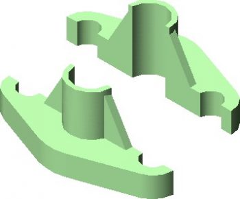
Solid modeling is a core feature of CAD software because it enables the creation of precise models of physical objects, not just 3D representations. It creates 3D representations that carry volume and mass, so you can run stress analysis directly on the model. Most CAD software uses parametric modeling to establish functional relationships between design elements. These relationships update connected features automatically and reduce manual errors (PTC's Pro/ENGINEER introduced parametric feature-based modeling in 1987, and SolidWorks brought it to Windows PCs in 1995).
How precise is a CAD model in practice
Digital design carries more precision than any process will reproduce, so the number that matters is the tolerance you write on the drawing. Most machine shops hold a standard tolerance of about ±0.005 inches (±0.13 mm) on milled and turned features. Published general-tolerance classes work differently: ISO 2768-1 scales the band with the size of the feature, so its medium class allows ±0.1 mm up to 6 mm, ±0.2 mm from 6 to 30 mm, and ±0.3 mm from 30 to 120 mm. CAD produces precise designs with tolerances as tight as 0.001 inches (0.025 mm), and shops reach that band with careful setup and slower cutting speeds in a temperature-controlled room. If the part is below ±0.0005 inches, it is usually sent to the mill for a secondary operation, such as grinding.
Every tightened callout adds cost. Apply the standard band to general features and reserve ±0.001 inches for the dimensions that govern fit or function. In the United States, ASME Y14.5 governs how you express geometric dimensioning and tolerancing on the drawing.
Examples of CAD software
AutoCAD is part of the broader family of computer-aided design software used in architecture, engineering, and construction, and its strength is producing detailed drawings and blueprints; like other CAD software, its functionality varies across modeling, simulation, and manufacturing. Its DWG format is the de facto standard for 2D drawing exchange.
SolidWorks focuses on mechanical design and parametric modeling. It shipped in November 1995 as the first professional-grade 3D CAD tool built natively for Windows, which moved 3D modeling off UNIX workstations and onto ordinary PCs. Dassault Systèmes acquired it in 1997.
Fusion 360 from Autodesk, launched in 2013, combines 3D modeling, simulation, and manufacturing into a single cloud-connected package, with direct support for CNC machining and 3D printing, though the extent of these capabilities varies across CAD software.
CATIA started in 1977 as an in-house surface modeler at Avions Marcel Dassault, built to design the Mirage fighter. It was renamed in 1981 when Dassault Systèmes was founded, and Boeing selected it as its main 3D CAD tool in 1984. It remains the reference for large aerospace and automotive programs.
FreeCAD is an open-source parametric modeler aimed at mechanical design and geometric constraints, useful when license cost is the binding constraint.
| Package | Primary use | First release | Notable fact |
|---|---|---|---|
| AutoCAD | 2D drafting and blueprints, architecture and construction | 1982 | Its DWG format is the de facto standard for 2D drawing exchange |
| Pro/ENGINEER (now Creo) | Parametric, feature-based solid modeling | 1987 | First commercially successful parametric associative modeler |
| SolidWorks | Mechanical design and parametric modeling | November 1995 | First professional-grade 3D CAD built natively for Windows; Dassault Systèmes acquired it in 1997 |
| CATIA | Large aerospace and automotive programs, class-A surfacing | 1977 in-house, renamed 1981 | Boeing selected it as its main 3D CAD tool in 1984 |
| Fusion 360 | Modeling, simulation and CAM in one cloud-connected package | 2013 | Cheapest route from model to CNC toolpath |
| Onshape | Cloud-native CAD and PDM | 2015 | Runs in a browser with automatic version history; PTC acquired it in November 2019 |
| FreeCAD | Mechanical design and geometric constraints | Open source | Useful when licence cost is the binding constraint |

The evolution of CAD software
CAD software traces back to the 1960s, when computers were first used for engineering computation. Six decades later, the geometry kernels are different; the interaction model is recognizably the same.
The birth of CAD tools
Ivan Sutherland submitted his MIT doctoral thesis, "Sketchpad: A Man-Machine Graphical Communication System," in January 1963. The program ran on the TX-2 computer at MIT Lincoln Laboratory and allowed a user to draw and manipulate shapes on the screen with a light pen. Sketchpad stored geometric constraints and solved them, so a user could instruct the system to keep two lines parallel, and the drawing would adjust itself. Compared with manual drawing, this made revisions faster and more precise. That mechanism is the direct ancestor of parametric CAD. Sutherland received the Turing Award in 1988 for his work.
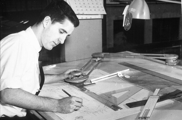
Engineering calculations were not yet linked to CAD software, though the digital path was open. Autodesk released AutoCAD in 1982 and published the DXF specification alongside it, so drawings could move between programs.
The shift to 3D modeling (1980s to 1990s)
PTC released Pro/ENGINEER in 1987, the first commercially successful parametric, associative, feature-based solid modeler. Design intent moved into the model itself through parameters and constraints, and a dimension change propagated across dependent features. SolidWorks followed in 1995 and brought the same paradigm to Windows PCs at a fraction of the cost, putting 3D modeling within reach of small and medium-sized companies.
Simulation integration (2000s)
At the turn of the millennium, computer software for computer-aided engineering brought analysis directly into the CAD environment. Engineers could evaluate structural integrity and fluid behavior during design rather than after prototyping. Computer-aided engineering reduced the number of physical articles a program needed, and design engineers could test and refine more variants earlier, though traditional workflows still relied on meshing 3D geometry for finite element and CFD simulations. Advances in graphics improved visualization, and because cloud computing was not yet available, simulations ran on private compute clusters.

Cloud-based CAD and additive manufacturing (2010s)
Autodesk released Autodesk 360 in 2012 and Fusion 360 in 2013. Cloud platforms allowed distributed engineers to open the same document and shortened the design process for distributed teams. Onshape arrived in 2015 as the first fully cloud-native CAD and PDM system, running in a browser with no local installation and automatic version history; PTC acquired it in November 2019. CAD packages added direct connections to 3D printers, supporting rapid prototyping before full production, and CFD on remote clusters lowered the IT cost of simulation.
Key features of computer-aided design
Parametric design drives geometry from named parameters. The model updates when a dimension or a relationship changes, so the design stays consistent with the rules you defined and speeds the engineering process when revisions cascade through the model.
2D and 3D modeling produce both the flat layouts and the volumetric models. The 3D model shows how an object looks and functions; the 2D CAD drawing carries the measurements that a machinist reads.
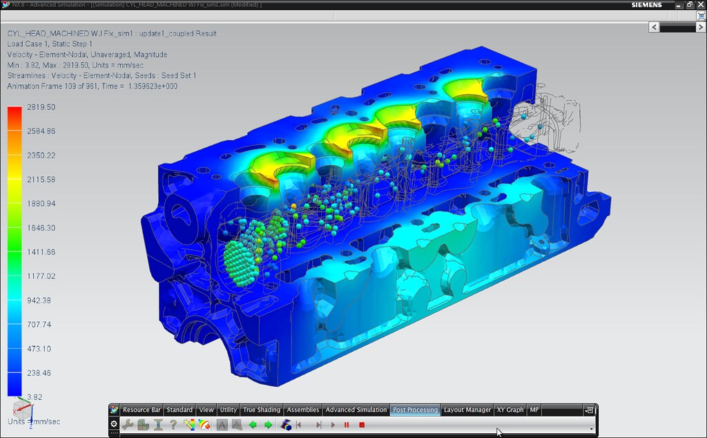
Simulation capabilities put the model under load before any part exists, covering structural stress and thermal behavior. Virtual testing reduces the number of physical prototypes and shortens the validation loop.
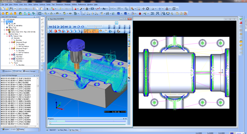
CAM software converts models into G-code or other machine-specific instructions for CNC equipment. It defines the toolpath and cutting speed for each operation, whether the process removes or adds material. Integrating computer-aided manufacturing with CAD removes the manual translation step, so automated systems on the shop floor work from the released geometry, and the same model data supports downstream manufacturing processes.
Collaboration tools keep concurrent work consistent. PLM systems manage product data throughout the product lifecycle. CAD integrates with PLM for version control and change tracking and links models to bills of materials, ensuring manufacturing data stays accurate.
PLM also automates design approval and compliance checks. Siemens Teamcenter and Dassault Systèmes ENOVIA serve industries that require strict data synchronization, such as automotive and aerospace.
Cloud-based features give access to CAD software and design data over the internet, so an engineer in one location can open and modify the same model as a colleague in another.
Computer-aided design in the automotive industry
The automotive industry adopted CAD early and pushed its capabilities to the limit. Vehicle programs now run on digital geometry from the first concept surface to the final assembly line.
Concept design and styling
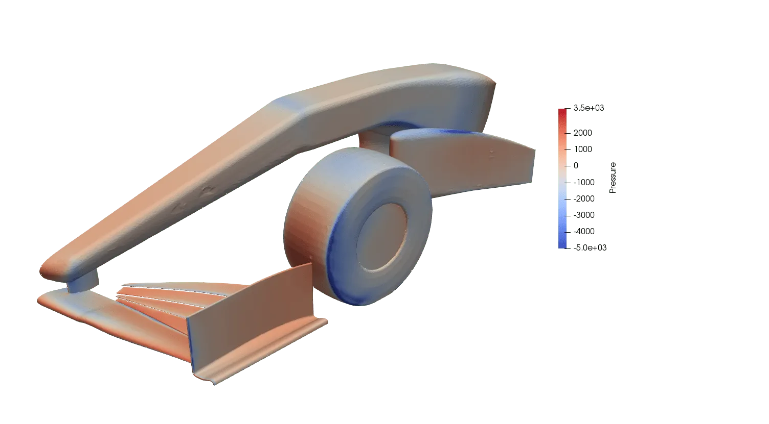
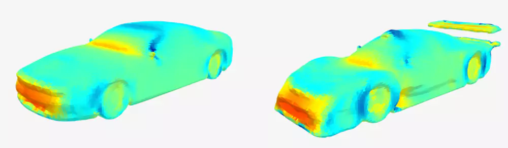
CAD and simulation tools shape a vehicle's exterior form. Designers model alternative proportions and surfaces, and generative design generates multiple optimized designs based on goals such as aerodynamics or weight; they review them from any angle, and product designers refine the brand's design language. Simulation checks aerodynamic and structural behavior early, which moves the program to the next phase without late rework. Direct prediction from geometry has removed much of the meshing work that used to sit between styling and analysis.
Manufacturing process and assembly
In manufacturing, 3D models enable CAD engineers to identify assembly interference before it reaches the production line. Simulations validate production sequences before parts arrive, and AI-enhanced CAE tools used in the automotive industry optimize designs for crash safety, aerodynamics, and energy efficiency before tooling is committed.
CAD software also supports manufacturing processes such as stamping and welding. Precise measurements and configurations reduce material waste, while these models help engineers optimize designs for custom tooling and fixtures, improving production accuracy.
Applications of CAD technology in other industries
How do CAD software tools serve other sectors, and what do recent advances in 3D Deep Learning add?
Aerospace
Innovations in Aerospace product design depend on CAD for accuracy and throughput.
CAD creates 3D models of aerospace components such as wings. A wing model carries through aerodynamics simulation and structural analysis, and the same geometry drives the weight accounting that runs from concept to assembly. For spacecraft, CAD defines modules and docking mechanisms and supports trajectory and fuel studies.
Material properties are modeled for certification evidence, and CAD supports the tooling design required for lightweight composite parts. Aerospace also drives the strictest interoperability rules, because a wing structure crosses dozens of suppliers before it flies.
After delivery, a digital twin links CAD models to operational data to improve performance monitoring. ISO 23247, published in 2021, defines the framework: the twin continuously updates operational and environmental data from its physical counterpart, supporting real-time control and predictive maintenance. The CAD geometry supplies the shape; sensor streams supply the state.

Architecture and construction
Digital technology lets architects and engineers test a design before construction starts. Energy performance is the clearest case: you simulate the building's daylight and thermal behavior on the model, then revise the facade, and the revision still costs nothing.
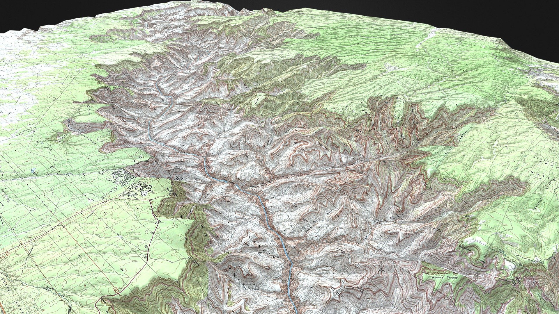
Civil engineers create representations of infrastructure on topographic and cadastral maps to plan and optimize engineering projects. BIM and GIS integration supports this workflow, allowing you to fit a bridge model to real terrain for accurate placement and design optimization.
Benefits of CAD technology
Computer-aided design provides precise tools for creating and refining digital models. The main returns are these:
• Accuracy and repeatability. Parametric relationships enforce consistency across a model, and the same geometry drives inspection and machining. Tolerances down to ±0.001 inches on critical features are specified in CAD and held in production.
• Cost savings in prototyping and manufacturing. Virtual prototypes replace most physical iterations. Simulation helps streamline workflows by reducing expensive late-stage changes before tooling is cut, at which point those changes become expensive.
• Shared design data. Cloud platforms and neutral file formats let engineers at different companies work from a single definition of the final product, shortening feedback cycles between the design process and the supply chain.
Common challenges and limitations
Consider a small or medium enterprise setting up a technical drawings office to support its product development. What will it run into?
Learning curve
SolidWorks and CATIA require substantial training. Engineers need time to master parametric modeling and assembly design, which slows initial output and adds training cost.

Initial costs of CAD tools
Professional CAD software carries license and hardware costs. For a small company, those compete directly with other capital spending.
Interoperability issues
Different CAD tools use proprietary native formats, so exchanging designs between platforms results in information loss. A STEP export preserves geometry and drops the feature tree, and the receiving engineer gets a solid without design intent. Companies working with external partners often need additional translation software, which adds cost and another potential point of failure.
What will the future of CAD technology be?
Data-driven prediction is changing how the model is used, and in some cases, how it is created.
Integrated simulation with artificial intelligence
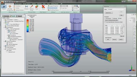
CAD supports simulations such as finite element analysis and fluid dynamics, which surface problems early and reduce prototyping costs, for instance, in the design of rotating machinery.

Can machine learning extend those capabilities by bringing high-fidelity computer-aided engineering into the CAD loop? Consider the scenarios described in AI in mechanical engineering.
A physics-aware AI model learns from previous simulation results and predicts the engineering attributes of a new shape directly from its geometry. Deep learning networks operating on 3D geometry predict fluidic and mechanical properties without meshing and solving each variant.
The effect on the workflow is measurable. You stop waiting hours for a solver run and get a prediction in seconds, which changes how many alternatives you can afford to evaluate.
This lets engineers explore the design space widely and converge on higher-performing products, with a shorter path from concept to result.
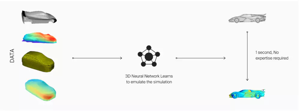
Methods based on 3D CNNs predict likely design weaknesses and optimize geometry from learned patterns.
Predictive models let designers evaluate how design variations behave under specified conditions, including unconventional shapes that no one would spend a solver run on. Simulation tools typically require specialist knowledge; embedding trained models in the CAD environment broadens access to analysis. As you modify a shape, the system returns feedback fast enough to guide the next edit.
Furthermore, AI can make everyday work easier. AI can generate CAD models from text descriptions and drawings. AI-assisted CAD speeds up design processes by automating repetitive tasks.
.png)
VR and AR integration
Virtual reality places you inside the digital model at full scale, so you can judge clearance and reach before a mock-up exists. Automotive studios use it for full-scale design review, where a screen would flatten proportions. Augmented reality overlays digital information on physical hardware, and service technicians use it for maintenance and troubleshooting.
Signed distance fields: new frontier
Signed distance fields define shapes with a mathematical function instead of boundary representation, which describes a solid by the surfaces and edges that bound it. The function returns a distance: positive outside the shape, negative inside, zero on the surface. Boolean operations and offsets that are fragile in B-rep become straightforward.
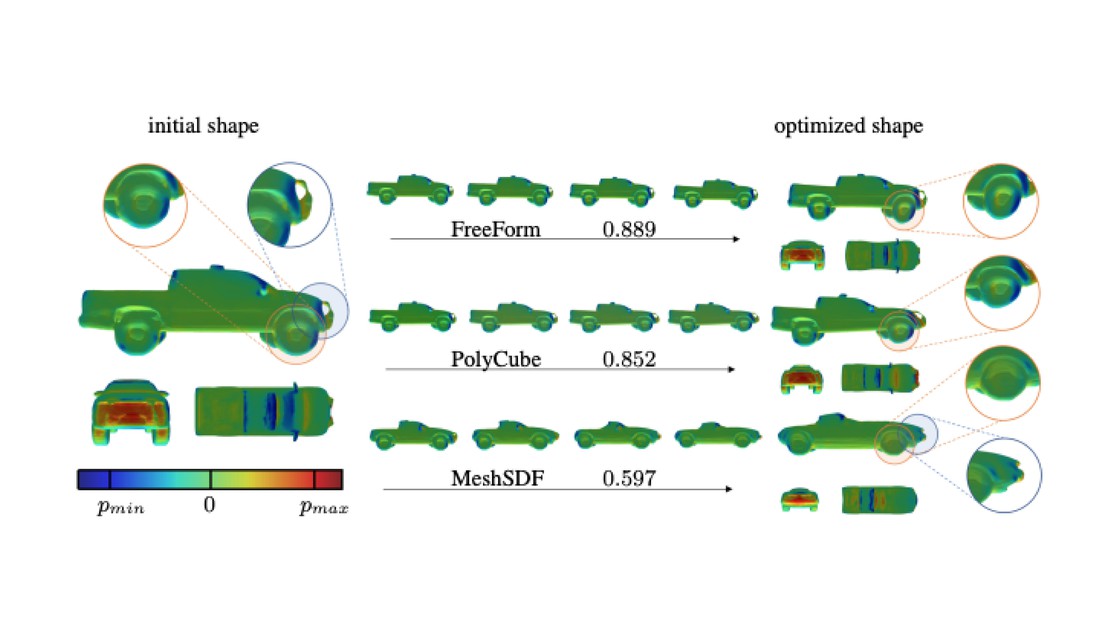
SDFs are established in specialist tools such as nTop for lattice structures and lightweight aerospace components. Mainstream adoption is slower because an SDF lacks an explicit topology, and integration with existing PLM and drawing workflows is more difficult. Broader adoption would change how large assemblies are handled and how simulation meshes are generated.
Conclusions
Computer-aided design has moved from being a replacement for drafting to becoming the definitive record for a product. It gives you precise models, virtual validation against real-world conditions, and a direct link to manufacturing.
The next stage adds trained models to that foundation. Machine learning predicts performance from geometry in seconds, generative methods propose shapes a person would not draw, and digital twins keep the model useful after the product ships.
The measurable returns remain the prototype cost avoided and the dimensional accuracy held in production, and those are the reasons CAD will continue to sit at the center of engineering work.
From CAD geometry to predicted performance
The mechanism above changes one thing in practice: when the evaluation happens. A physics-aware model trained on a company's own simulation archive reads the CAD geometry directly and returns the performance figure, so a shape is judged while it is still being edited rather than after a queue on the solver. Neural Concept delivers this as an Intelligence Layer for Engineering for physical products, sitting above the CAD and CAE tools already in place, with an AI Design Copilot that answers inside the design loop.
Subaru applied it to die face shape design, where the analysis time fell from three hours to two minutes. MAHLE explored 30 million design iterations on a radial blower and reached 15% higher efficiency with 4 dB less noise, a design space no run-by-run process would have covered. In both cases the CAD model stayed the source of truth; what changed was how fast a new shape could be judged.
Ready to judge a design while the geometry is still on your screen?
Explore the platform →FAQ
What's the difference between parametric CAD and direct modeling, and why do engineers choose one over the other?
Parametric CAD builds a part as an ordered history of features. Each sketch and every feature built from it is recorded in a tree, and dimensions and constraints tie them together. Changing a hole diameter and all dependent features triggers a rebuild. PTC introduced the approach commercially with Pro/ENGINEER in 1987, and SolidWorks, Inventor, Creo, NX, CATIA, and Onshape all use it.
Direct modeling discards the history. You push and pull faces and edges on the geometry itself, and the edit takes effect immediately with no rebuild.
Choose parametric for production parts and for any design that will go through many controlled revisions. Choose direct modeling for early concepts and for imported STEP files, which arrive without a feature tree. Fusion 360, Creo, and the Siemens tools support both, so you can model quickly and add structure as the design matures.
SolidWorks vs. AutoCAD vs. Fusion 360 vs. CATIA: Which is best for mechanical and aerospace design?
AutoCAD is a drafting tool first. Use it when the output is 2D technical drawings and DWG deliverables.
SolidWorks is the common choice for mid-size mechanical design, including assembly design, sheet metal work, and accompanying drawings. It has the largest pool of trained users.
Fusion 360 combines modeling, CAM, and simulation into a single subscription package. It is the cheapest route from model to CNC toolpath and is well-suited for small companies.
CATIA handles large assemblies, class-A surfacing, and strict configuration management, which is why airframe and vehicle OEM programs run on it. Boeing has used it since 1984. License and training costs are correspondingly high.
For general mechanical design, SolidWorks. For aerospace structures inside an OEM supply chain, CATIA is often used because the customer specifies it in the contract.
What CAD file formats are used for cross-platform interoperability (DWG, DXF, STEP, IGES), and when should each be used?
DWG is Autodesk's proprietary binary format for AutoCAD. It preserves every AutoCAD feature and stays lossless inside the Autodesk ecosystem. Autodesk does not publish the specification, so other programs read it through reverse-engineered libraries.
DXF is Autodesk's documented text-based exchange format, published since 1982. Almost every CAD, CAM, and CNC package reads it, which makes it the safe choice for sending 2D profiles to a cutter.
STEP (ISO 10303) is the modern neutral 3D format. AP242 is the current reference application protocol and carries semantic product manufacturing information, including GD&T and datums, which supports drawingless manufacturing. Use STEP for solid geometry crossing a vendor boundary, and expect the feature tree to be lost in transit.
IGES dates to 1980 and stopped at version 5.3 in 1996. It carries surfaces and curves without a watertight solid concept, an assembly hierarchy, or tolerancing. Use it only when a legacy system on the other end cannot accept STEP.
How does CAD fit into the broader CAD/CAM/CAE/PLM product development workflow?
CAD defines the geometry and the design data. CAE takes that geometry and predicts behavior: stress, vibration, flow, thermal response. CAM converts the same geometry into toolpaths and G-code for manufacturing equipment. PLM holds versions and bills of materials, as well as the approval records that prove a given revision was signed off.
The working sequence is model, validate, release, manufacture, and feed measurement back. The value comes from associativity. When the CAD model changes, the mesh, the toolpath, and the BOM should all flag as out of date rather than remain silently stale. Siemens Teamcenter and Dassault Systèmes ENOVIA manage that link in automotive and aerospace programs.
Cloud-based CAD vs. on-premise workstations: what are the trade-offs?
Cloud CAD removes installation and version conflicts. Onshape launched in 2015 as the first fully cloud-native CAD and PDM system, and Fusion 360 follows a similar model. Everyone opens the same document, and edit history is automatic. In exchange, you depend on connection quality, your geometry sits on a vendor's servers, and export-controlled or defense work may prohibit that arrangement.
On-premise workstations give deterministic performance on large assemblies, full control of where design data resides, and offline capability. The cost is hardware refresh cycles and the IT time to administer license servers.
A common arrangement splits the two: cloud tools for concept work and external collaboration, on-premise systems for released programs under ITAR or customer data agreements.
What are the 4 types of CAD?
2D CAD creates flat layouts. 2.5D CAD adds prismatic depth without overhangs. 3D CAD builds full three-dimensional models, split into solid modeling for volumetric objects and surface modeling for freeform shapes. EDA, or electronic design automation, designs circuit boards and integrated circuits with dedicated tools for schematic capture, layout, and simulation.
What are CAD examples?
Examples include AutoCAD for 2D and 3D drawing, SolidWorks for mechanical 3D modeling, Revit for building design, and CATIA for complex engineering systems. Other packages target niches such as PCB layout and mold design.
Where is CAD mostly used?
CAD is used wherever a physical product gets manufactured, from aerospace to consumer goods. Vehicle design is the largest single application: every car on the road and every aircraft in the air were defined in CAD before they were built.
How does CAD differ from traditional drafting?
Computer-aided design and drafting allow revisions without redrawing, and they produce geometry that downstream systems can consume directly. It connects directly to CNC equipment and 3D printers, and it holds exact measurements in two and three dimensions. Manual drafting produces a drawing; CAD produces a model from which the drawing is derived.
Sources
Ivan E. Sutherland, Sketchpad: A Man-Machine Graphical Communication System, PhD thesis, Massachusetts Institute of Technology, January 1963. MIT DSpace.
ACM A.M. Turing Award, Ivan Sutherland, 1988.
ISO 2768-1:1989, General tolerances — Part 1: Tolerances for linear and angular dimensions without individual tolerance indications.
ISO 10303-242:2020, Industrial automation systems and integration — Product data representation and exchange — Part 242: Application protocol: Managed model-based 3D engineering (STEP AP242).
ISO 23247-1:2021, Automation systems and integration — Digital twin framework for manufacturing — Part 1: Overview and general principles.
ASME Y14.5, Dimensioning and Tolerancing.
Appendix — abbreviations
CAD — computer-aided design; CADD — computer-aided design and drafting
CAE — computer-aided engineering
CAM — computer-aided manufacturing
PLM — product lifecycle management; PDM — product data management
B-rep — boundary representation, a solid described by its bounding surfaces and edges
NURBS — non-uniform rational B-spline, the mathematics behind freeform surfaces
SDF — signed distance field
GD&T — geometric dimensioning and tolerancing; PMI — product manufacturing information
FEA — finite element analysis; CFD — computational fluid dynamics
CNC — computer numerical control
BIM — building information modelling; GIS — geographic information system
EDA — electronic design automation