Neural Concept Connect 2026 · Bay Area ✓ · Next: Munich (Nov 24) · Tokyo (Feb 3, 2027)Apply for your spot
How to Calculate Heat Dissipation to Prevent Overheating
A
Anthony Massobrio
CFD Expert & AI for CAE Contributor
16 min read·Published ·Updated
In short
Engineering systems generate heat, and components fail when it is not carried away. Heat has identifiable sources, it must be dissipated, and the thermodynamic laws supply practical formulas for calculating heat and power dissipated, up to detailed 3D simulation of a full system.
Key takeaways
Heat leaves a component in three ways: conduction, convection, and radiation.
High-performance CPUs and GPUs reduce their clock speeds when temperatures approach their rated limits, protecting the silicon at the cost of performance.
Long periods at high temperatures age materials faster, accelerating fatigue cracking and corrosion.
A widely used rule of thumb holds that every 10 °C above the rated temperature roughly halves a component's service life.
Table of contents
Heat dissipation is calculated by dividing the temperature difference between a component and its surroundings by the thermal resistance of the path between them: Q = (Tⱼ – Tₐ) / Rₜₕ. When the power draw is known instead, the same relation yields the temperature rise: ΔT = P × Rₜₕ. Both expressions size a cooling solution in minutes. Hot spots, airflow, and geometry require three-dimensional simulation.
Heat dissipation is the process of transferring or dispersing heat generated by components in an engineering system to prevent overheating and failure. For engineers and designers working on thermal performance in electronics and industrial equipment, that means understanding where heat comes from, why it must be removed, and how to size the right cooling approach before reliability, efficiency, and service life are compromised.
This article covers the concept of heat dissipation through practical formulas, thermodynamic principles, and both overall system calculations and detailed 3D simulation. It is designed to help engineers evaluate heat generation, calculate dissipated heat and power, compare cooling measures, and use advanced CAE and AI-supported methods to protect the performance and longevity of electronic systems and industrial equipment. The intended readers are thermal and electronics designers sizing heat sinks and enclosures, CAE engineers running conjugate heat transfer studies, and engineering managers evaluating where AI shortens the thermal design loop.
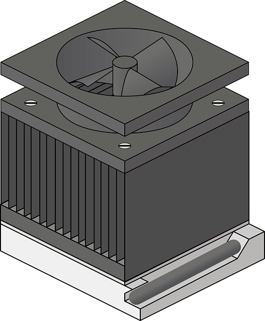
A finned heat sink with a fan: conduction into the fins, then forced convection into the air
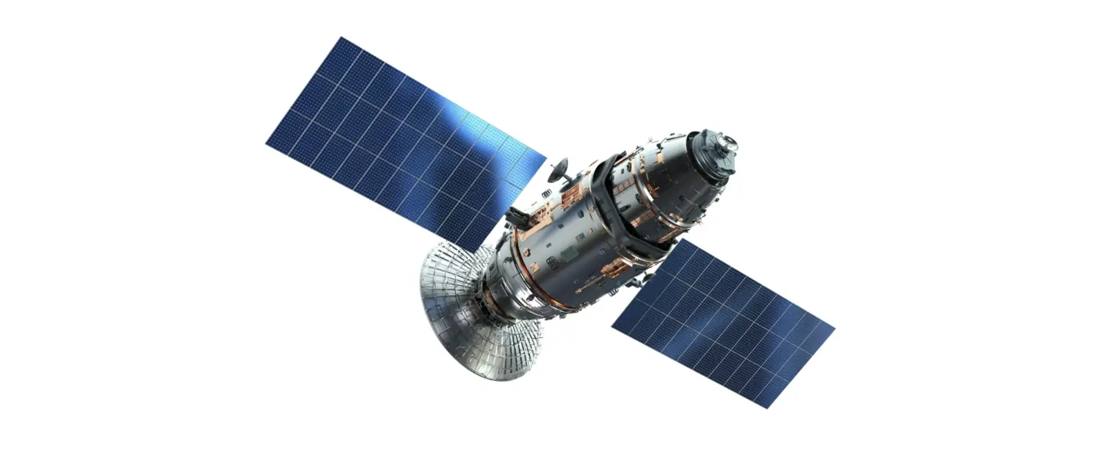
One critical example is the cooling of artificial satellites, where efficient heat dissipation is crucial for mission success. Without an effective satellite cooling system design, the electronic components could fail, compromising the entire mission. The same issue applies to all electronic devices. This emphasizes the importance of dissipating heat to maintain optimal operating conditions and prevent failures.
Another example of the need for heat dissipation is the switchgear, i.e., the electrical equipment used to control and protect power systems. It typically includes circuit breakers, disconnect switches, and fuses. Inadequate heat dissipation in the system can lead to overheating, causing various problems. Excessive heat can deteriorate insulation materials, reducing their lifespan and potentially leading to insulation breakdown or flashovers. Overheating can also compromise the mechanical integrity of switchgear components, leading to malfunctions or failures.
To illustrate the “What-Why-How” of the entire process, from heat generation to heat dissipation, we will start with an example of an electric power supply.
What is creating heat generation?
In electric power supplies, various components are typically used, such as transformers, rectifiers, capacitors, and semiconductors. These components generate heat due to their internal resistance, switching losses, and power dissipation.
Why should heat be dissipated?
If the heat generated is not adequately dissipated, it can lead to a temperature rise, thermal stress, and potential damage to the system and its surrounding components. Effective thermal managementis essential to maintain the system temperature within safe operating limits, ensure reliability and efficiency, and extend its lifespan. More will be explained in the next Thermodynamics section.
Two consequences follow directly. High-performance CPUs and GPUs throttle processing speeds to avoid damage, reducing clock frequency and voltage once the junction reaches its rated limit. Intel sets a limit between 100 °C and 110 °C for most current processors and states that activating the thermal control system typically causes a measurable performance loss. Prolonged thermal stress can accelerate material fatigue and corrosion: repeated expansion and contraction crack solder joints and interfaces, while elevated temperatures speed oxidation reactions that degrade insulation and metal surfaces.
A rule of thumb derived from the Arrhenius equation quantifies the cost. Every 10 °C increase in operating temperature above the rated value approximately halves the service life of electrical insulation and many electronic components. The rule is an approximation and ignores failure modes unrelated to peak operating temperature, but it explains why a few degrees of thermal margin justify substantial investment in cooling.
How can heat be dissipated?
Design engineers employ various cooling techniques and design considerations to optimize heat exchange, with conduction, convection, and radiation as the primary heat dissipation mechanisms. A few basic practical strategies for optimal heat dissipation are described below:
Heat Sinks: They are commonly used in power supplies to increase surface area for heat transfer, with copper and aluminum preferred for better heat dissipation. These metallic structures help dissipate heat by increasing the contact area with the surrounding air, enhancing convective heat transfer.
Fans and Ventilation Openings: They can facilitate airflow and enhance convective heat dissipation by increasing the mass flow rate of air or other cooling fluids, thereby carrying away heat generated by the components. The mass flow rate is the mass of fluid (air) passing through a specific area per unit of time. By utilizing fans and ventilation openings, the mass flow rate of air can be increased, leading to more efficient heat transfer. The higher the mass flow rate, the more heat can be carried away from the components. This increased airflow helps reduce component temperatures and keep them within their safe operating limits. In practice, fans create forced convection, while natural convection occurs as warm air rises on its own. By actively promoting a higher mass flow rate through the system, fans and ventilation openings play a crucial role in preventing overheating and ensuring optimal performance of electronic devices.
Liquid Cooling: In high-power systems, liquid cooling circulates coolant to maintain safe temperatures, often through components such as cold plates.
Materials: Using thermal interface materials, such as thermal pads or compounds, improves thermal conductivity between the heat source and heat sinks, enhancing thermal dissipation efficiency. Metals, ceramics, and graphite are also common choices in thermal design. A vapor chamber can also spread heat efficiently due to its very high thermal conductivity.
Specific Heat: When a component or system generates heat, the specific heat of the surrounding materials affects how quickly and efficiently the heat is dispersed or transferred to the environment. Specific heat allows engineers to calculate the amount of heat energy required to raise a substance’s temperature, as well as the amount of heat energy that can be released when its temperature decreases. Engineers can select appropriate materials for heat sinks, heat exchangers, or other cooling components to optimize heat dissipation.
Enclosure Design: The design of an enclosure can also impact heat dissipation. Proper ventilation, strategically placed vents, and heat-conductive materials can help dissipate heat effectively.
The balance between these strategies has shifted as power density has increased. Air cooling was designed for server racks drawing 8-12 kW. An NVIDIA GB200 NVL72 rack draws 120 kW to 132 kW, and the Vera Rubin platform pushes rack requirements toward 246 kW. Average rack density across the industry increased from approximately 16 kW in 2025 to 27 kW in 2026. At the upper end of that range, air cannot reject the heat at all, and direct-to-chip liquid cooling becomes a requirement rather than an option.
The laws of thermodynamics
Effective heat dissipation is important in electronic devices. Think of computers and smartphones. The same is true in industrial applications, such as power plants and manufacturing facilities. Heat dissipation is related to the principles of energy conservation and the increase of entropy. Those principles are outlined in the first and second laws of thermodynamics.
The first law of thermodynamics
The first law of thermodynamics states that energy cannot be created or destroyed; it can only be transferred or converted from one form to another. In the context of heat dissipation, the first law of thermodynamics states that the heat generated by a system must be transferred to the surroundings to conserve energy.
The second law of thermodynamics and entropy
The second law states that in any energy transfer or conversion, the total entropy of an isolated system will either remain constant or increase.
Heat dissipation is a direct consequence of the second law of thermodynamics, which describes entropy and the direction of energy flow. The heat generated within a system is sensitive to temperature differences and tends to flow from higher- to lower-temperature regions, seeking equilibrium. Bodies also emit thermal radiation as infrared electromagnetic energy into the surrounding environment, so thermal energy spreads not only through temperature-driven conduction and convection but also through radiation. This natural tendency to reach thermal equilibrium represents the increase in entropy as heat energy spreads out and becomes more disordered. Effective heat dissipation mechanisms facilitate this process by allowing heat energy to flow from the source (higher temperature) to the surroundings (lower temperature), thereby increasing entropy and maintaining overall system balance.
Heat dissipation formulas
For specific situations such as electronic devices, total heat dissipation can be expressed with simplified calculation formulas. Applications can be integrated circuits (ICs), transistors, or microprocessors. With this calculation, engineers can determine the amount of heat generated and design cooling systems accordingly. In addition to thermal-resistance-based estimates, engineers also use the convection relation Q = hA(Tsurface – Tair) to calculate convective heat transfer. This helps prevent overheating and ensures the reliable operation of electronic devices. The following formula depends on surface area, air temperature, and the heat transfer coefficient.
Heat dissipation formula (examples for electronic engineers)
The following practical formulas are examples commonly used by electronic engineers to calculate heat dissipation in electronic devices:
Heat sinks are a common thermal design element in electronic devices, including CPUs, and can handle heat fluxes exceeding 100 W/cm².
For material choice, copper has a thermal conductivity of about 401 W/m·K, whereas graphene can exceed 4000 W/m·K, offering better heat dissipation.
How to calculate heat dissipation using thermal resistance
This formula calculates the heat dissipation (in W) based on the temperature difference between the junction and ambient, divided by the thermal resistance of the component:
Q = (Tⱼ – Tₐ) / Rₜₕ
In this formula:
Tⱼ refers to the junction temperature of the component, while Tₐ represents the ambient temperature (°C)
Rₜₕ is the thermal resistance of the component, measured in degrees Celsius per watt (°C/W).
This conductive heat flow follows Fourier’s Law along the heat dissipation path from the heat source into the surrounding structure, and both thickness and contact area influence conduction, thereby improving heat dissipation.
How to calculate the heat dissipation using power and thermal resistance
This formula calculates the temperature rise across a thermal path from the power consumption P (W) and the component’s thermal resistance Rₜₕ. In steady state, all electrical power drawn by a component leaves it as heat, so the heat dissipated equals the power consumption:
ΔT = P × Rₜₕ, and therefore Tⱼ = Tₐ + P × Rₜₕ
A device drawing 15 W through a junction-to-ambient resistance of 4 °C/W runs 60 °C above ambient. Inside a 40 °C enclosure, the junction reaches 100 °C, which equals the throttling threshold of most current silicon.
Formula
What it gives
Inputs
Worked example
Q = (Tⱼ − Tₐ) / Rₜₕ
Heat dissipated, in W
Junction and ambient temperature in °C, thermal resistance in °C/W
A 60 °C rise across 4 °C/W carries 15 W
ΔT = P × Rₜₕ, so Tⱼ = Tₐ + P × Rₜₕ
Temperature rise across the path, and the resulting junction temperature
Power drawn in W, thermal resistance in °C/W
15 W through 4 °C/W runs 60 °C above ambient; in a 40 °C enclosure the junction reaches 100 °C
Q = hA(Tₛᵤᵣfₐᶜₑ − Tₐᵢᵣ)
Convective heat transfer from a surface
Heat transfer coefficient, surface area, surface and air temperature
Sizes the fin area a heat sink needs for a target surface temperature
In higher-power cases, air cooling may be insufficient, whereas liquid cooling uses a coolant and can remove heat at rates exceeding 300 W.
Heat dissipation calculations: CAE simulation & AI
The previous lumped formulas are useful for the overall sizing of components, but they are “lumped” (zero-dimensional) overall balances of a system that provide no details of what is happening at specific locations in space. Therefore, for detailed heat dissipation computations, CAE (computer-aided engineering) simulation is essential for analyzing and optimizing the thermal performance of various systems and components in full 3D, coupled with digital CAD (computer-aided design) representations of their geometry.
Whether the subject is a satellite panel, an electronic device, or industrial equipment, understanding how heat is dissipated and managed is essential for ensuring reliable operation and preventing potential issues such as overheating.
The issues with traditional CAE approaches are the investment in hardware, the skills engineers need to run the application software, and the wait time for simulation results, which motivates using deep learning applications in engineering design workflows.
A solution aiming to increase efficiency in the design department was to train an AI-based physics-aware model for thermal transfer in satellite panels. The model was integrated into a CAD platform so that designers could modify geometries and obtain thermal results in real time as they made changes.
Satellite panel thermal design, the case used to train the physics-aware thermal model
Neural Concept extended the approach in 2026 with a physics- and geometry-aware AI design copilot that connects to multi-physics simulations, including thermal management, and which the company reports reduces manual workload in early design by up to 90 percent.
The practical consequence is a change in where engineering time is spent. The effectiveness of deep learning in thermal transfer simulation is measured in the number of geometries evaluated per unit of engineering time, and that number is no longer constrained by solver cost. Thermal performance becomes a design variable considered from the first sketch rather than a constraint verified at the end.
Thermal performance as a design variable
The lumped formulas above size a cooling solution before anything is drawn. The 3D question, where the hot spot actually sits once the geometry is real, is the one that used to arrive too late to change the design. A model trained on a company’s own thermal simulations reads the geometry and returns the temperature field directly, which is what turns thermal performance from a constraint verified at the end into a variable steered from the first sketch. Neural Concept delivers this as an Intelligence Layer for Engineering for physical products, above the CAD and CAE tools already in use, with an AI Design Copilot that answers while the geometry is still open.
The pattern holds wherever a thermal path gates the design. Eaton applied it to cooling plates and gained more than 30% in pressure drop and more than 10% in weight. MAHLE designed a radial blower for automotive HVAC by exploring 30 million design iterations, reaching 15% higher efficiency with 4 dB less noise. Neither replaces the solver; both change how many thermal layouts can be judged before one is committed.
Ready to see the temperature field while the geometry is still a choice?
CDU — coolant distribution unit, used in direct-to-chip liquid cooling
SEI — solid electrolyte interphase, the layer whose decomposition starts thermal runaway
TSV — through-silicon via, used as a thermal path in 3D-stacked circuits
FAQ
What is the difference between active and passive cooling methods?
Passive cooling moves heat without consuming power, relying on conduction into a heat sink, natural convection, and radiation. Active cooling adds a powered device such as a fan or a pump to force fluid movement. Active methods handle much higher heat flux, while passive methods have no moving parts and produce no acoustic noise, making them suitable for sealed enclosures and long-service equipment.
How is heat dissipated in lithium-ion batteries, and how is thermal runaway prevented?
Cells generate heat from internal resistance and from the entropy change of the electrode reactions. Battery thermal management systems remove heat using air, liquid cold plates, or phase-change materials, keeping cells within the 20 °C to 40 °C window where lithium-ion chemistry remains stable. The specific case of thermal runaway in EV battery packsillustrates how internal short circuits, elevated temperatures, and overcharging can trigger catastrophic failures if not properly managed. Thermal runaway begins when the solid electrolyte interphase decomposes at roughly 80 °C to 120 °C, and separator melting near 130 °C to 150 °C then produces internal short circuits and a self-sustaining cascade. Prevention combines cell-level temperature monitoring, thermal barriers that block propagation between cells, and vent paths that release gas before pressure causes the pack to rupture.
What thermal management approaches are used for high-power LED lighting systems?
High-power LEDs convert most of their electrical input into heat at the junction, and that heat leaves through the package rather than with the light beam. The standard path runs from the die through a metal-core printed circuit board, a thermal interface material, and an aluminum heat sink. Luminaires with high flux density incorporate heat pipes or vapor chambers to spread the heat load. Junction temperature governs lumen depreciation and color shift, so it is the design target rather than case temperature.
How does heat dissipation apply to building design and HVAC systems?
Building cooling loads combine internal gains from occupants, lighting, and equipment with solar gain through glazing and conduction through the envelope. HVAC capacity is sized against the peak of that combined load. Passive measures reduce it before mechanical cooling is engaged. External shading and envelope insulation limit the gain, while thermal mass shifts the peak later in the day, and night ventilation purges the stored heat.
What's the difference between a vapor chamber and a heat pipe for cooling electronics?
Both are sealed two-phase devices containing a wick and a working fluid, and both move heat by evaporation at the hot end and condensation at the cold end. A heat pipe is a tubular device that transports heat along one axis, typically from a processor to a remote fin stack. A vapor chamber is planar and spreads heat in two dimensions, reducing the spreading resistance that appears when a small, high-flux die meets a much larger heat sink base.
How does ambient temperature affect heat sink effectiveness?
Heat sink performance depends on the temperature difference between the fin surfaces and the surrounding air, not on absolute temperature. Its thermal resistance in °C/W remains approximately constant, so for a fixed dissipated power, the component temperature increases by about 1 °C for each 1 °C rise in ambient temperature. The result is a direct loss of margin against the junction temperature limit. Reduced air density at altitude further lowers convective capability, so heat sinks specified at sea level are derated for high-altitude installations.
What's the difference between thermal paste, thermal pads, and adhesive TIMs?
Thermal paste forms the thinnest bond line and gives the lowest thermal resistance, but it requires mechanical clamping and can dry out or pump out under thermal cycling. Thermal pads are thicker and compressible, so they absorb assembly tolerances and gaps that paste cannot fill, at the cost of higher resistance. Adhesive thermal interface materials bond the component to the heat sink mechanically, eliminating the need for clips or screws but making rework difficult.
What heat dissipation challenges arise in 3D-stacked integrated circuits?
Stacking increases power per unit volume while the area available for heat removal remains the same. Heat generated in a lower die conducts through the dies above it before reaching the heat sink. The bonding and dielectric layers between tiers have low thermal conductivity, so they act as thermal barriers. Hot spots appear where high-power logic is located farthest from the cooling surface. Design responses include thermal through-silicon vias, floorplanning that places the highest-power blocks nearest the heat sink, and research into microfluidic channels etched between tiers.
Sources
Intel, processor thermal specifications and thermal monitoring: the junction temperature limit above which the thermal control system reduces frequency and voltage. Published on intel.com per processor family.
IEC 60085, Electrical insulation — Thermal evaluation and designation: the standard behind the rule of thumb that each 10 °C above the rated temperature approximately halves insulation life, itself derived from the Arrhenius relation.
NVIDIA, GB200 NVL72 — the rack-scale platform whose power draw is quoted here.
Neural Concept, AI Design Copilot, 7 January 2026 — the multi-physics connection covering thermal management, and the reduction of manual workload by up to 90% in early design.
J. B. J. Fourier, Théorie analytique de la chaleur, 1822 — the conduction law applied along the heat dissipation path.