A cold plate is a liquid-cooled heat exchanger: heat from high-power components is conducted through a metal plate into a coolant circulating in internal channels. Cold plate design specifies the plate material, channel geometry, and coolant flow rate to keep component temperatures within their limits while maintaining an acceptable pressure drop. (Jiga; reference 1).
Key takeaways
Cold plate: a liquid-cooled heat exchanger mounted on high-power components.
Thermal engineers and CFD or FEA analysts: the governing equations and the geometric parameters that set cold plate performance, with their trade-offs.
Heads of engineering: the simulation time of each cold plate variant, and the use of AI prediction to shorten design iterations.
CTOs and R&D directors: the dependence of high-power electronics, EV batteries, and AI servers on liquid cooling.
Cold plates remove heat from sensitive components where air cooling cannot keep up. As devices shrink and power density rises, liquid cooling becomes the only viable option.
This article covers the three drivers of cold plate performance: heat transfer, flow optimization, and material selection. It focuses on engineering principles and simulation-driven design. Product sizing and supplier comparisons are out of scope.
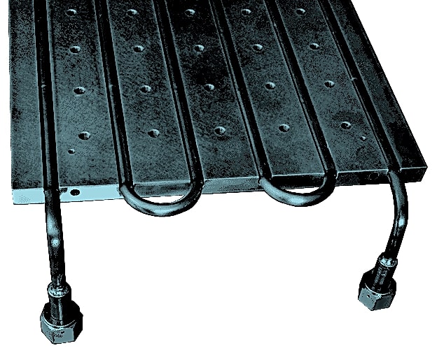
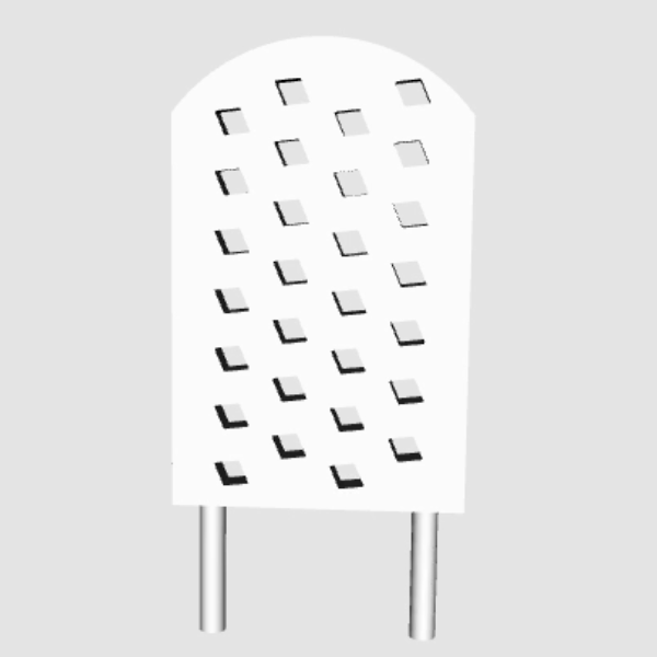
The figure shows a liquid cold plate, in this case with U-turns in the channels that route the liquid into and out of the plate. A cold plate is a localized heat-removal system that transfers heat from a specific location to a remote heat exchanger. The remote heat exchanger eventually dissipates the heat.
As shown in the figure, the cold plate is connected to a larger system via inlet and outlet plugs. The liquid cooling system operates as a circuit. The circuit comprises the cold plate, which is in contact with the heat source, a pump that circulates fluid throughout the system, and a heat exchanger (HX). The HX ultimately releases thermal energy from the liquid, often with the help of a forced-convection device (a fan).
We review airflow and liquid cooling principles, key design parameters, and system integration with remote heat exchangers. High heat loads threaten mission-critical systems from satellites to data centers. Cold plate design is now a core engineering discipline.
We also cover simulation and AI-driven prediction methods that accelerate cold plate design before physical prototyping.
Industrial examples of cold plate usage for thermal management
Examples of systems that use a cold plate include automotive, aerospace and defense, and various energy and machinery applications.
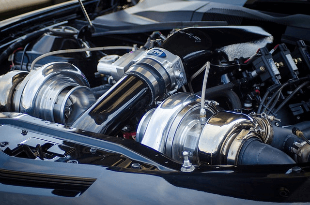
Both of the following cooling methods are used for vehicle thermal management, either traditionally in internal combustion engine (ICE) vehicles or in EVs:
Air cooling: fans dissipate thermal energy (this article uses the term as a synonym for “heat”) via forced convection. In EVs, some designs apply air cooling to the electric motor and power electronics, such as inverters and DC-DC converters.
Liquid cooling: a coolant (water or a specialized liquid) removes heat from the battery cells, engine, or other overheated components. Liquid cooling is characterized by better transfer and removal of excess thermal energy. However, the coolant may undergo critical events, such as boiling. Boiling represents a local deterioration of thermal performance and is prevented by design.
Li-ion battery cells’ high energy density and thermal energy generation in EVs make liquid-cold-plate cooling an efficient choice for maintaining the battery’s temperature within an optimal range. Liquid coolant circulates through channels or tubes integrated into the battery pack. The coolant absorbs the high heat loads through a liquid cold plate.
These two cooling methods are frequently employed individually or in combination to effectively regulate temperature.
Radiators with integrated fans exemplify combined air and liquid-cooling. The radiator dissipates heat from the liquid circuit; a pump circulates coolant through the system.
Aerospace and defense cold plate cooling examples
Aerospace electronics liquid cooling: Aerospace applications, including avionics and satellite systems, can rely on cold plates to control the temperature of critical electronic systems under the harsh conditions of space and high-altitude flight. While liquids can be used in space for cooling and heat transfer, the mechanisms and systems are adapted to the unique microgravity and vacuum environments.
Military and defense electronics: Military applications, including radar systems and communication equipment, often integrate liquid cooling systems and cold plates to maintain the operational readiness of electronic components in extreme ambient or operating conditions.
Energy machinery cold plate cooling examples
Industrial power electronics:Industrial machinery and power electronics often incorporate liquid cold plates to cool high-power semiconductors, such as insulated-gate bipolar transistors (IGBTs) and thyristors, when space is limited. This cooling arrangement ensures efficient operation of high-power electronics at high heat loads.
Cold plate application in renewable energy inverters: Inverters in renewable energy systems, such as solar or wind power converters, rely on cold plates for efficient cooling. Efficient cooling enhances the energy conversion efficiency and extends the lifespan of critical components.
ICT applications: cold plate cooling examples
Role of the cold plate in telecommunications infrastructure: Cold plates are employed in data centers and telecommunications infrastructure to manage the heat generated by networking equipment. This heat removal ensures uninterrupted data transmission and system reliability.
Role of the cold plate in high-performance computing (HPC) clusters and data center cooling: An HPC cluster is a powerful computing infrastructure that handles computationally intensive tasks, simulations, scientific calculations, and data analysis. Cold plates and tubes are integrated into HPC clusters to cool powerful processors and high-density memory modules. This cooling sustains computational performance.
The role of cold plates is crucial in HPC clusters and data center cooling due to the high heat loads generated by computations and other operations on both CPUs and GPUs. In data centers, cold plates mounted directly on high-power chips, such as AI accelerators and server processors, provide direct-to-chip cooling for heat loads beyond the capacity of air cooling (Eaton; reference 2).
Heat conduction in air or liquid cold plates
Cold plates use conduction through the metal plate to efficiently transfer heat from heat sources to the cooling fluid (gas or liquid).
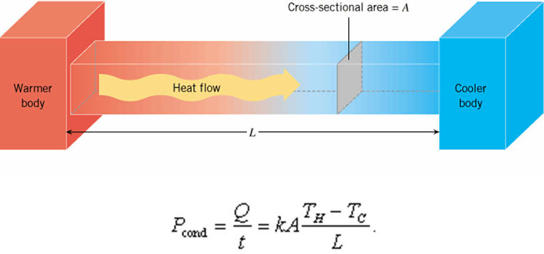
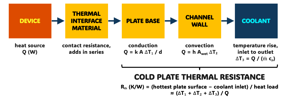
The quantity of interest is the rate Q (in W) at which thermal energy is transferred, expressed as a function of the solid material’s thermal properties (such as the cold plate material’s conductivity, its cross-sectional area, and its thickness). This relationship applies to the design of heat sinks, the calculation of insulation effectiveness, and the sizing of components in thermal management systems in which conduction is critical.
The relationship is Fourier’s law of heat conduction, in W:
Q = k A ΔT / d
k: thermal conductivity of the cold plate material, in W/m·K
A: cross-sectional area for heat transfer, in m²
d: thickness of the cold plate, in m
ΔT: temperature difference across the plate thickness, between the face in contact with the thermal source and the channel wall, in K
In the gradient form of the law, q = −k ∇T, the minus sign indicates that heat flows from higher to lower temperature (Incropera, DeWitt, Bergman and Lavine, 2011; reference 3).
At the channel wall, heat passes from the metal to the coolant by convection, according to Newton’s law of cooling: Q = h A ΔT. Here, “h” is the convective heat transfer coefficient, “A” is the wetted heat transfer area, and “ΔT” is the temperature difference between the channel wall and the coolant.
In more complex geometries or situations involving non-uniform temperature distributions, this one-dimensional form of Fourier’s law may need to be adapted or replaced with more complex equations, such as the conduction equation in cylindrical or spherical coordinates, to accurately model the transfer of thermal energy, or even with CAE (Computer-Aided Engineering) software for numerical solutions.
Material selection in cold plates
The thermal conductivity of the plate material determines the temperature drop due to conduction across the cold plate. Materials with high thermal conductivity, such as copper or aluminum, are commonly used for their ability to conduct heat efficiently. For example, pure copper has a thermal conductivity (k) of over 400 W/m·K at room temperature (Incropera, DeWitt, Bergman and Lavine, 2011; reference 3). The value for pure aluminum is about 237 W/m·K.
Copper’s thermal conductivity is second-highest (after silver) among pure metals at room temperature. Copper’s excellent electrical conductivity parallels its thermal conductivity.
The thermal properties of these materials determine the effectiveness of the cold plate solution. Material selection also involves corrosion resistance and manufacturability, including additive manufacturing enhanced by AI-driven design for complex internal geometries when conventional machining or joining is restrictive. Each wetted material in the loop is chosen for compatibility with the coolant (Ecotherm; reference 4):
Copper: higher thermal conductivity, about 385 W/m·K at 20 °C for the copper grades used in data center cold plates, at a higher weight and generally a higher cost (Ecotherm; reference 4).
Aluminum: lightweight and less costly, used for large plates and EV systems, but prone to galvanic corrosion when coupled with copper in a loop without an appropriately inhibited coolant (Boyd; reference 5).
Basic fluid dynamics and flow optimization of cold plates
Engineers design the internal passages within cold plates to optimize coolant flow. Fluid dynamics principles, including the incompressible Navier-Stokes equations, are instrumental in designing passages that facilitate efficient transfer and minimize pressure drop (ΔP).
In words, the momentum balance per unit volume reads:
For incompressible flow, it is solved together with the continuity equation ∇ · v = 0, in which:
ρ: density of the coolant (in most cases constant)
v: velocity vector in the coolant, with three components, one per spatial direction
p: pressure
μ: dynamic viscosity of the coolant (the coolant can be water or another liquid with more suitable properties)
g: gravitational acceleration (some systems operate under microgravity conditions)
∇: gradient vector operator; ∇² is the Laplacian operator, applied here to each velocity component
Flow instability, modeling and control
A unique solution for the flow requires boundary and initial conditions for both velocity and pressure.
Numerical solution of this system of equations, usually with Computational Fluid Dynamics (CFD) methods, provides the velocity and pressure distribution in the computational flow domain over time. In a cold plate simulation, the energy equation is solved in the coolant and in the solid, together with the flow equations in the coolant.
For flow in a liquid-cooled plate, the equation is simplified based on the specific geometry and boundary conditions. In most cases, the simplification involves assumptions such as:
Steady-state flow: the time-dependent term ∂v/∂t is ignored.
Incompressible flow:ρ is constant.
Body forces: gravity (g) is neglected for horizontal cold plates.
The choice of boundary conditions, such as the inlet velocity (set by the coolant flow rate) and pressure, will also depend on the cold plate’s specific design and operating conditions.
A higher coolant flow velocity improves thermal performance and increases pressure drop. For instance, a CFD study examined a 20 Ah lithium-ion pouch cell cooled by cold plates on both faces (Patil, Panchal, Kim and Lee, 2018; reference 6). In this study, a fourfold increase in coolant mass flow rate improved temperature uniformity and increased the pressure drop by 1124%. The cooling efficiency, defined in the study as the heat removed per unit of pumping power, decreased as the flow rate increased.
Analytical solutions to the full Navier-Stokes equations are challenging or impossible for most practical engineering problems involving complex geometries, unsteady flow, turbulence, or multiphase flow. Numerical methods, such as Computational Fluid Dynamics (CFD), are essential for solving and analyzing fluid flow. CFD discretizes the governing equations and solves them numerically over a computational domain. This discretization makes it possible to handle a wide range of real-world scenarios.
Prediction with CFD and AI
Ideally, simulation tools would be integrated into design tools such as CAD and would return the quantities of interest to the designer without delay. For an HX, these quantities are:
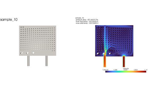
CAD ==> [max temperature in the solid, max temperature in the fluid, pressure loss ΔP in the system]
However, in practice, with CFD or FEA tools, the time indicated by the arrow “==>” corresponds to hours or days per design variant.
Data: the large amounts of simulation data accumulated by engineers over the years.
Deep Learning: models fitted on these stored cases map the geometrical details of an HX to the associated temperature, velocity, and pressure fields, from which the thermal performance KPIs are extracted.
Thus, for a new shape within the range of geometries covered by the stored cases, designers obtain the required engineering KPIs without waiting for a full CAE run. A new design outside that range still requires a CFD or FEA simulation. The result of that simulation extends the stored cases.
As a practical example, Eaton applied Neural Concept’s deep learning to its own cold plate design data. According to Neural Concept, the resulting workflow reduced pressure drop by 30% or more and weight by 10% or more in cooling modules. On the geometry side, the Neural Concept AI Design Copilot generates manufacturing-ready 3D geometry options from design intent.
Heat exchanger efficiency
Liquid cold plates essentially function as an HX. The effectiveness of the heat exchanger can be quantified using the effectiveness-NTU (Number of Transfer Units) method. The method accounts for the heat capacity rates of the streams exchanging heat.
The effectiveness ε is the ratio of the actual heat transfer rate to the maximum possible rate, a measure of heat transfer efficiency. Between two fluids, ε depends on NTU, on the capacity-rate ratio Cᵣ = Cₘᵢₙ / Cₘₐₓ, and on the flow arrangement (Incropera, DeWitt, Bergman and Lavine, 2011; reference 3).
In a cold plate, the coolant exchanges heat with a wall that is approximately uniformly heated. This wall behaves as a stream with an infinite capacity rate. Thus, Cᵣ = 0 for a cold plate. For Cᵣ = 0, every flow arrangement reduces to the same relation:
ε = 1 − exp(−NTU)
The Number of Transfer Units (NTU) is a dimensionless parameter that accounts for the heat-transfer surface area, the overall heat transfer coefficient (U), and the coolant flow rate: NTU = U A / (ṁ cₚ), in which ṁ is the coolant mass flow rate and cₚ is its specific heat. It quantifies the relative size of the HX and characterizes its thermal efficiency.
Custom cold plate design: optimization challenges
The previous sections describe the basic physical principles underlying a liquid cold plate. The design of custom liquid cold plates involves conceiving a geometry that provides optimal thermal performance, and these plates are tailored to application-specific mechanical envelopes and thermal requirements.
The cold plate and other advanced thermal solutions in thermal management are heavily based on specific geometric configurations. Engineers apply geometrical design criteria to tailor cold plates for diverse applications, from high-performance computing to industrial equipment. A thermal engineer balances geometry, allowable pressure drop, and manufacturability during custom design. A well-designed cold plate efficiently removes high heat loads and ensures the reliability and longevity of critical components within thermal management systems.
The overall shape of the liquid cold plate is tailored to fit the specific thermal source and system constraints. Whether flat, curved, or customized to fit a particular component, the geometry is designed to ensure efficient thermal contact.
Thermal interface materials (TIMs) replace the air in the microscopic gaps between the component and the plate. Air has a thermal conductivity of only about 0.026 W/m·K.
The TIM therefore reduces the contact resistance between the cold plate and the heat source (Ecotherm; reference 7).
Cold plates also operate under internal coolant pressure. For instance, in a hybrid vehicle power module, Eaton sized the liquid cold-plate thickness to withstand operating and test pressures and validated the design on prototypes (Eaton; reference 8). Structural integrity is therefore a design criterion alongside thermal performance.
The following subsections describe the key geometrical design criteria for cold plates.
Cold plate channel geometry and layout
The configuration and dimensions of the internal channels within the liquid cold plate significantly affect its performance.
Engineers design these channels, considering factors such as width, depth, and spacing, to maximize heat transfer over the wetted heat transfer area under the heat source. A uniform distribution of coolant across the liquid-cooled plate maintains an even temperature field.
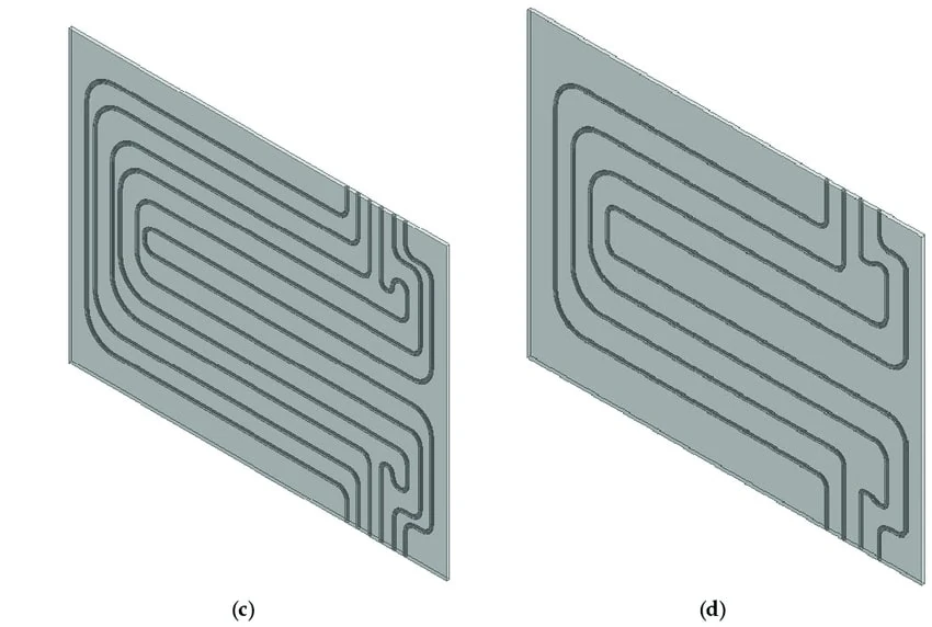
Cold plates with different numbers of cooling channels for a 20 Ah lithium-ion pouch cell | source: “Cooling Performance Characteristics of 20 Ah Lithium-Ion Pouch Cell with Cold Plates along Both Surfaces” (Patil, Panchal, Kim and Lee, 2018; reference 6)
The shape of the channels, whether rectangular, circular, or other profiles, can affect the velocity distribution, the temperature gradients across the plate, and ΔP. Optimization of the cross-sectional geometry increases the thermal energy removed by the liquid cold plate at a given pressure drop. For instance, in the same pouch cell study, reducing the number of channels from 10 to 4 increased the pressure drop by 466.8% (Patil, Panchal, Kim and Lee, 2018; reference 6).
The cross-section sets the hydraulic diameter Dₕ = 4 A / P, in which “A” is the flow cross-sectional area and “P” is the wetted perimeter (Incropera, DeWitt, Bergman and Lavine, 2011; reference 3). In fully developed laminar flow, the Nusselt number “Nu” is constant, and the convective heat transfer coefficient h = Nu · k / Dₕ increases as Dₕ decreases (Ecotherm; reference 4). In this relation, “k” is the thermal conductivity of the coolant.
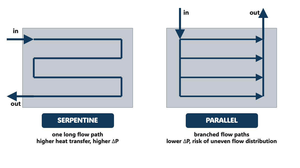
Engineers explore various channel layouts, such as serpentine or parallel configurations, to efficiently distribute coolant and ensure uniform heat distribution. A serpentine channel routes the whole flow through a single long flow path. This layout improves heat transfer and increases pressure drop. Parallel channels reduce pressure drop but risk uneven flow distribution between branches (Ecotherm; reference 4).
Fin structures in heat exchanger design
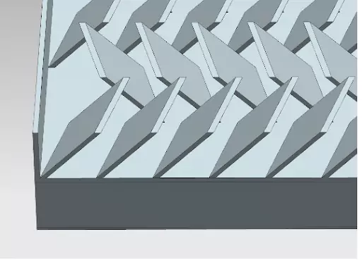
Fin structures increase the available surface for heat dissipation. The geometry of these fins, including height, thickness, and spacing, is tailored to the specific application’s thermal requirements.
The main fin parameters contribute to an optimized liquid- or air-cooled cold plate design as follows:
Fin height: the height of the fins, measured perpendicular to the cold plate’s surface, is adjusted to balance the need for increased area with practical considerations such as the available space within the cold plate. Taller fins generally provide a greater exchange area. Beyond a certain height, the added area contributes little heat transfer, because fin efficiency decreases with fin height (Ecotherm; reference 4).
Fin thickness: the dimension parallel to the cold plate’s surface is fine-tuned to optimize heat conduction and distribution. Proper thickness ensures efficient thermal coupling between the hot components and the cooling liquid or air flowing through the channels.
Fin spacing: narrower spacing between individual fins increases the convective heat transfer coefficient (HTC) and the resistance to liquid or air movement. The chosen spacing balances the two effects.
Inlet and outlet locations
Positioning the coolant’s inlet and outlet ports on the cold plate can influence liquid or air distribution and ΔP. Engineers place these openings to minimize flow imbalances and ΔP losses.
The coolant temperature rise between inlet and outlet follows from the energy balance ΔT = Q / (ṁ cₚ). A higher coolant flow rate reduces this rise and the temperature difference between the plate’s upstream and downstream regions.
Remote heat exchanger and secondary cooling system
Secondary cooling systems use liquid cooling solutions to dissipate the thermal energy absorbed by cold plates.
Secondary cooling systems may also involve additional HX or radiators to regulate the temperature of the cooling liquid further before it circulates back to the cold plates.
In summary, cold plate design determines the material, internal channels, and coolant flow of a liquid-cooled heat exchanger. A well-designed cold plate solution efficiently manages the thermal challenges posed by modern electronics, electric vehicle batteries, high-performance computing clusters, and various industrial applications. These solutions safeguard the longevity and integrity of critical parts, ensuring they operate within safe temperature limits while maintaining full system performance.
For efficient thermal management, simulation-driven optimization evaluates each custom thermal solution before a prototype is built. Within the range of stored cases, the physics-aware AI of Neural Concept, the Intelligence Layer for Engineering, returns the temperature and pressure fields of each variant in 0.1 to 1 second.
FAQ
How do you calculate pressure drop and thermal resistance for a cold plate design?
Cold plate datasheets commonly define thermal resistance as Rₜₕ = (Tₘₐₓ − Tᵢₙ) / Q, with units of K/W. Here, Tₘₐₓ is the maximum surface temperature under the heat source, Tᵢₙ is the coolant inlet temperature, and Q is the heat load. The resistance combines conduction through the base, convection at the channel walls, and the coolant temperature rise Q / (ṁ cₚ) (Incropera, DeWitt, Bergman and Lavine, 2011; reference 3).
Pressure drop is calculated during cold plate design because it determines pump selection and the cooling loop. The pressure drop in a straight channel follows the Darcy-Weisbach relation ΔP = f (L / Dₕ) ρV²/2, with f = 64 / Re for fully developed laminar flow in a circular tube. Bends, manifolds, and fittings add local losses. The operating point of the loop lies at the intersection of the pump curve and the system pressure drop curve (Eaton; reference 9). For complex internal channels, a conjugate heat transfer CFD simulation computes both quantities simultaneously.
Tube-in-plate vs. milled channel cold plates: what are the pros and cons of each?
Tube-in-plate: a coolant tube embedded in the plate. It offers simple construction, flexible tube routing, and low cost for moderate heat loads; the tube-to-plate contact adds thermal resistance (Ecotherm; reference 4).
Milled channel: channels machined by CNC machining into the base and sealed by a cover, joined by friction stir welding (for aluminum plates) or by vacuum brazing. It offers freedom in channel layout, with internal fins close to concentrated heat sources; however, the welding path, brazing quality, and part distortion require control (Ecotherm; reference 4).
Additive manufacturing can be used when very complex internal passages are needed, but cost, tolerances, and lead time should be compared with machined or brazed options.
Which materials are common for cold plates, and how do copper and aluminum compare?
Common materials for cold plates include copper and aluminum (KingKa; reference 12).
Copper: pure copper has a thermal conductivity of over 400 W/m·K at room temperature, the second-highest among pure metals after silver (Incropera, DeWitt, Bergman and Lavine, 2011; reference 3). Copper-brazed cold plates offer the highest thermal conductivity among common cold plate materials, and copper cold plates provide the lowest thermal resistance for high-power-density components (KingKa; reference 12).
Aluminum: aluminum alloys are often chosen for cost-sensitive and weight-sensitive designs, such as automotive, general electronics, and industrial automation (KingKa; reference 12). In a loop that also contains copper, aluminum requires an inhibited coolant (Boyd; reference 5).
How do internal microchannels and optimized flow channels affect cold plate performance?
Internal microchannels increase the surface area in contact with the fluid. The larger wetted area increases heat transfer (Ecotherm; reference 13). Narrow channels also increase flow resistance. Optimized flow channels minimize pressure drop at the required thermal performance. For instance, the Eaton cooling modules described above achieved a pressure-drop reduction of 30% or more, according to Neural Concept.
Water-glycol vs. dielectric fluid: how do the two coolant types compare?
Water-glycol mixtures have high specific heat and thermal conductivity, and the glycol lowers the freezing point; they are used with inhibitor packages to protect the wetted metals. Dielectric fluids, such as polyalphaolefin (PAO) and fluorocarbons, are electrically non-conductive, so a leak does not short-circuit the electronics. Their thermal conductivity is much lower: PAO has a thermal conductivity of about 0.14 W/m·K, so the same heat load requires a larger heat-transfer area or a higher flow rate (Eaton; reference 10). Dielectric fluids also allow immersion cooling, in which the fluid contacts the components directly.
What's the difference between direct-to-chip cooling and traditional cold plate designs for CPUs?
Direct-to-chip cooling is a cold plate application: a thermally conductive plate is placed directly against the processor (Eaton; reference 2). For GPUs and switch chips, these plates typically contain microgroove fins (Ecotherm; reference 4). Traditional designs cool CPUs with air heat sinks, or mount several components on a larger cold plate. Direct-to-chip plates address high-heat-flux components: Ecotherm reports heat fluxes exceeding 50 W/cm² for GPU and switch chips, with local hotspots reaching 150 W/cm² (reference 4).
How do you prevent galvanic corrosion in multi-metal liquid cooling loops?
Materials: the same metal, or metals with similar electrical potential, throughout the loop, such as an all-aluminum or all-copper wetted path (Boyd; reference 5).
Coolant: corrosion inhibitors in water-glycol loops to prevent galvanic corrosion. Inhibited glycol-water coolant is used rather than tap water; uninhibited ethylene glycol can degrade into acidic compounds that corrode metals (Boyd; reference 5).
Isolation: electrical isolation between dissimilar metals when a mixed-metal loop cannot be avoided (Penflex; reference 11).
Flow: a stable flow without stagnant zones within the cooling system (Boyd; reference 5).
What role do thermal interface materials (TIMs) play in cold plate assembly performance?
A TIM fills the microscopic air gaps between the component and the cold plate base. Air conducts heat poorly, with a thermal conductivity of about 0.026 W/m·K, so the TIM layer reduces the contact resistance between the cold plate and the heat source. A flat, finely machined base allows for a thinner TIM bond line and lower interfacial resistance (Ecotherm; reference 7). Greases, pads, and phase-change materials are common TIM types.
How does cold plate design differ for medical imaging equipment like MRI and CT scanners?
Medical imaging adds constraints beyond heat load, according to a cold plate manufacturer (Ecotherm; reference 7):
MRI gradient amplifiers: pulsed loads, absorbed by thick-base cold plates with tight temperature uniformity across the transistor array.
CT gantry electronics: components that rotate with the gantry, with reported accelerations up to 75 g, so joining methods such as friction stir welding are preferred for strength.
X-ray tubes: more than 99% of the electrical energy is dissipated as heat, which is removed via a dielectric oil loop and copper cooling blocks.
Safety and noise: touch-temperature limits under IEC 60601-1, low acoustic noise, and helium leak testing; surface treatments, such as clear anodizing of aluminum heat sinks, provide electrical insulation.
Sources
Jiga. What is a cold plate? A guide to cold plate design, manufacturing and applications. Jiga Resource Center, 2026. https://jiga.io/articles/cold-plate/
Patil, M. S., Panchal, S., Kim, N., and Lee, M.-Y. Cooling performance characteristics of 20 Ah lithium-ion pouch cell with cold plates along both surfaces. Energies, 11(10), 2550, 2018. https://doi.org/10.3390/en11102550