What Is Engineering Simulation Software and How it Works?
What is engineering simulation software and how does it work?
Engineering simulation software replaces physical prototypes with mathematical models and numerical methods. It predicts structural loads, fluid flow, and heat transfer before manufacturing begins.
Companies that use simulation software shorten design cycles, cut prototyping costs, and gain a competitive edge.
This article outlines the simulation process, the main categories of mechanical simulation software, and industry applications.
The article is dedicated to engineers selecting advanced simulation tools and program managers balancing accuracy with business strategy.
Physics domains in engineering simulation
Engineering simulation shapes most products before they reach the market.
Structural frames, thermal systems, and electronics are modeled and simulated before manufacturing. Tools predict performance under load, heat, and electromagnetic interference.
No simulation software covers all physical phenomena.
- Structural mechanics, heat transfer, electromagnetics, crashworthiness, and aerodynamics each rely on dedicated solvers. A Computer-Aided Engineering (CAE) specialist selects different solvers to address specific engineering challenges: finite element analysis (FEA) for structural mechanics and crash-test simulation, and computational fluid dynamics (CFD) for fluid flow. The specialist translates a Computer-Aided Design (CAD) model into a discrete representation the solver can process, then checks the output against real-world behavior.
- Some problems span multiple domains. Thermal simulations use FEA or CFD, depending on setup. Fluid-structure interaction can be coupled in a single analysis. High fidelity requires validation against analytical or experimental data, not visual resolution.
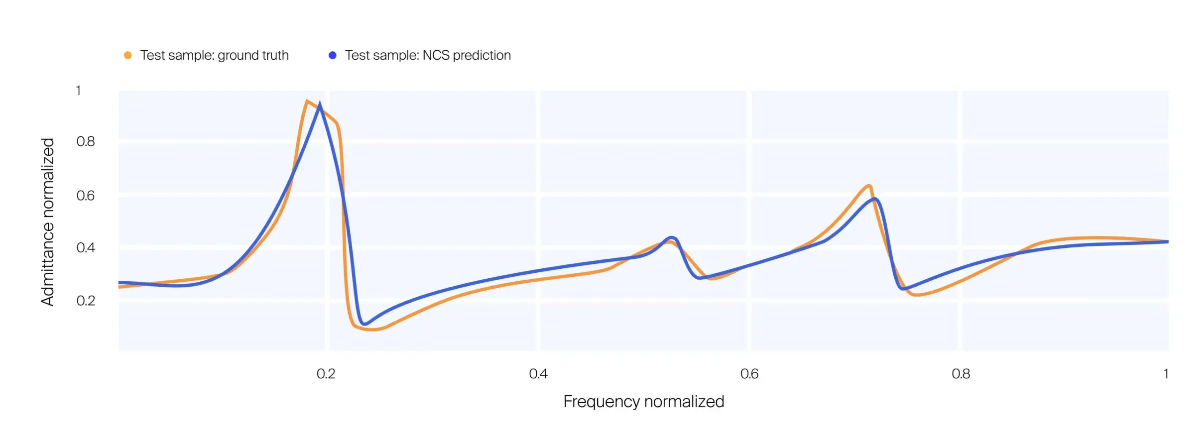
- AI models trained on simulation data deliver physics-aware predictions without running a full solver. Non-specialist engineers can evaluate designs on a laptop rather than on a compute cluster.
The simulation process
Simulation software is used early in the design phase and throughout the product development process, not just to replace physical wind tunnel tests. CAD models stand in for prototypes, boundary conditions replace wind-tunnel setups, and solvers replicate physical tests. The same approach applies to skyscrapers, aircraft, and industrial equipment.
- Input data: Simulation input data include material properties, environmental conditions, geometric dimensions, and boundary conditions. These values set simulation accuracy against real-world behavior.
- Mathematical modeling: Mathematical models, which underpin modeling and simulation, represent physical behavior in three dimensions. Accurate simulation depends on correct physical formulation and translation into equations. Engineers solve these equations for specific geometry and inputs.
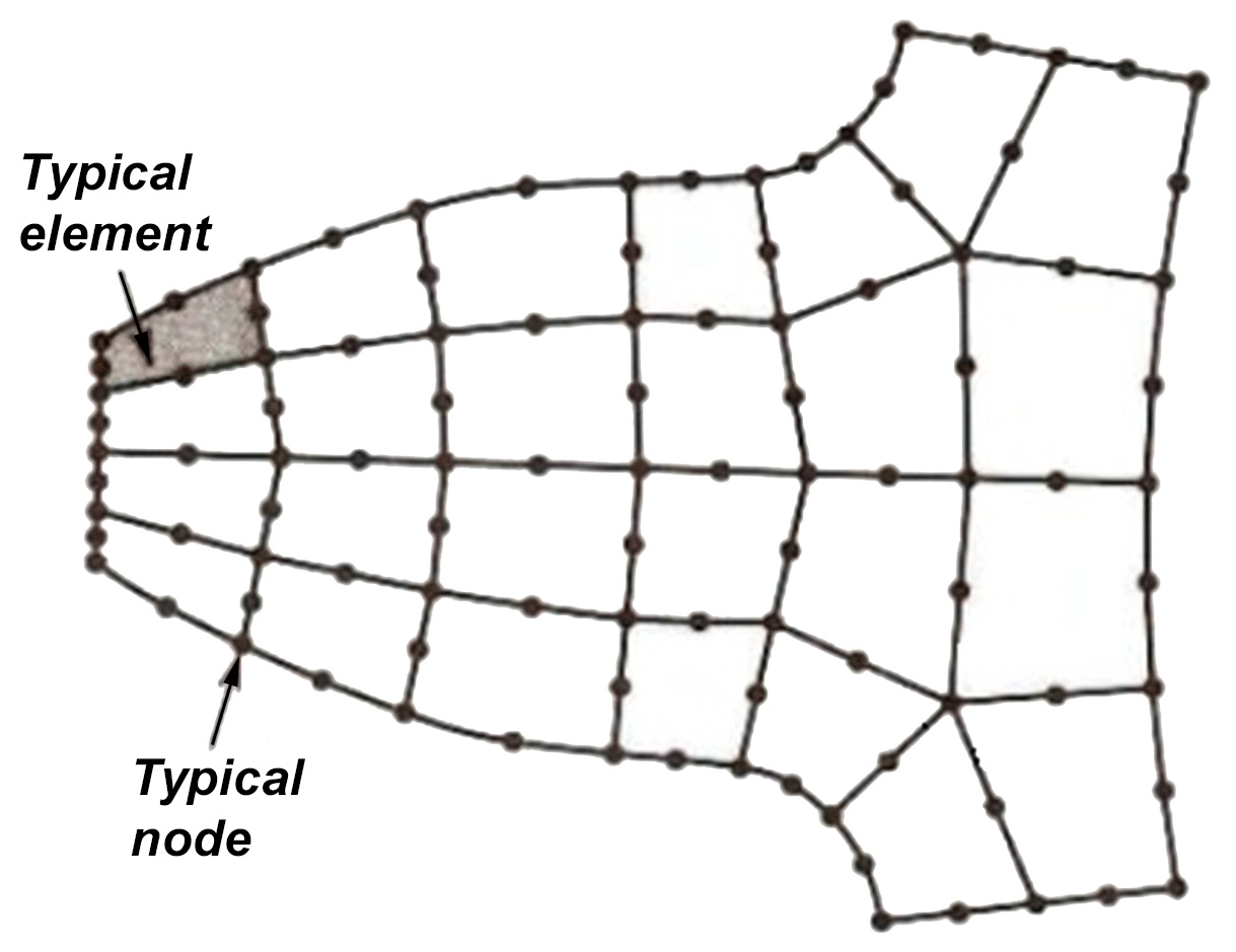
- Role of numerics: Analytical solutions exist only for a narrow set of cases, so software applies numerical algorithms to solve the governing equations for realistic geometries. Before a solver can process a design, it converts the geometry from the CAD environment into a mesh: a discrete representation of the continuum. Meshing strategy affects both computation time and simulation accuracy, and building a mesh well is a core skill for a CAE specialist.
- Hardware: Numerical methods run on CPUs or GPUs, local or cloud-based, and that same hardware now supports machine learning workflows alongside them. Hardware capacity sets simulation speed and the number of design iterations before the deadline. Faster hardware shortens simulation cycles but does not eliminate compute cost. AI models trained on simulation data reduce wait times from hours to milliseconds. Engineers evaluate product performance in real time without running a full solver for each variant.
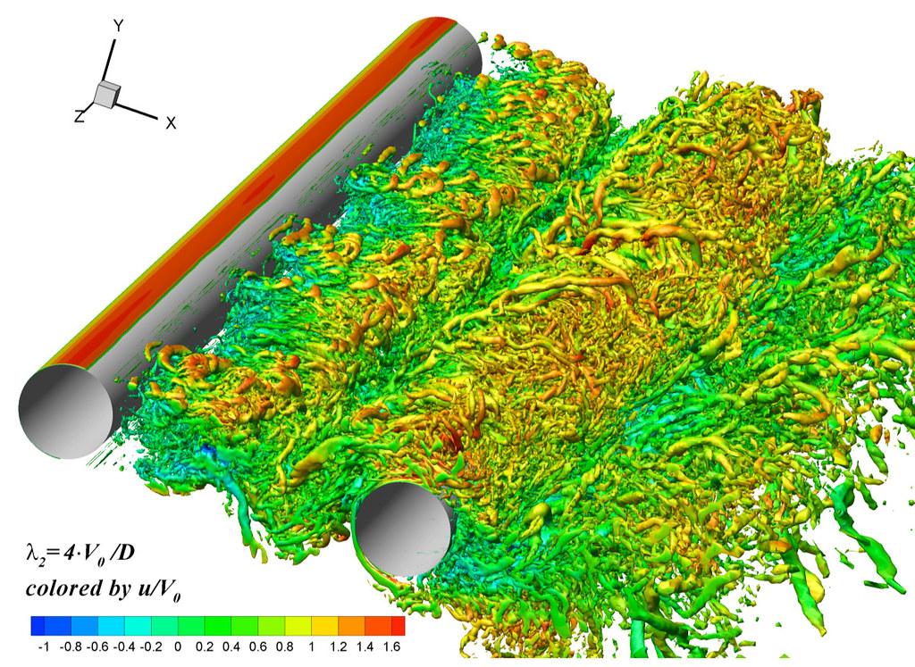
Key features of engineering simulation software
Modern simulation software automates setup with automatic mesh generation, built-in solvers, and streamlined interfaces. These features move decision-making earlier in the development process, before physical prototyping.
- Role of mathematical models: Mathematical models form the foundation of simulation software. They translate physical laws into equations. Equation accuracy sets the ceiling for simulation reliability.
- Equations and algorithms: Governing equations are formulated before software implementation. Solvers use algorithms such as finite element or finite volume methods. Simulation programs allow users to run analyses without deep mathematical knowledge, but results require review by someone who understands the physics.
- Boundary conditions: Boundary conditions constrain how a system interacts with its environment: displacement, velocity, temperature, or other physical quantities at the edges of the model. Running the same model against different boundary conditions in a sensitivity study shows how the design responds across operating scenarios that reflect real-world conditions.
- Initial conditions define the state of the system at the start of the simulation: starting velocities, temperatures, or other quantities. Depending on the physics involved, an inaccurate initial condition can be negligible or compound into a significant discrepancy in the predicted behavior.
Types of engineering simulation tools
Engineers can analyze the same product from multiple angles, with different tool categories helping engineering teams assess it across specialties. A vehicle can be evaluated for crashworthiness using finite element analysis or for aerodynamic performance using computational fluid dynamics, and each analysis uses a different tool and skill set to optimize performance within its own physics domain.
Finite element analysis (FEA)
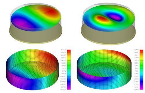
FEA divides geometry into discrete elements and solves for each using numerical algorithms. Engineers use FEA for structural mechanics, heat transfer, and solid material problems where structural integrity and stress are primary concerns.
Computational fluid dynamics (CFD) simulation tools
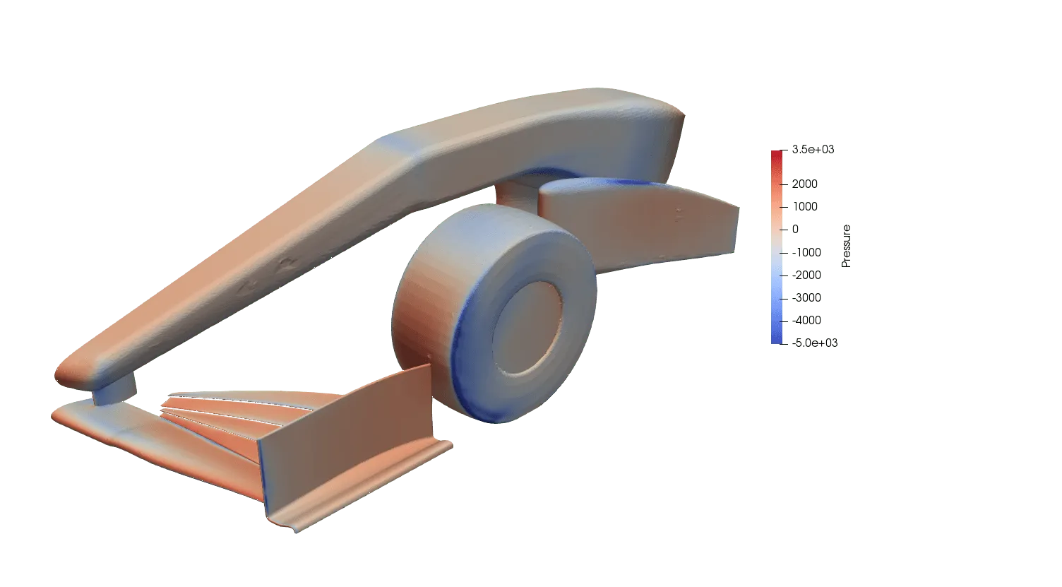
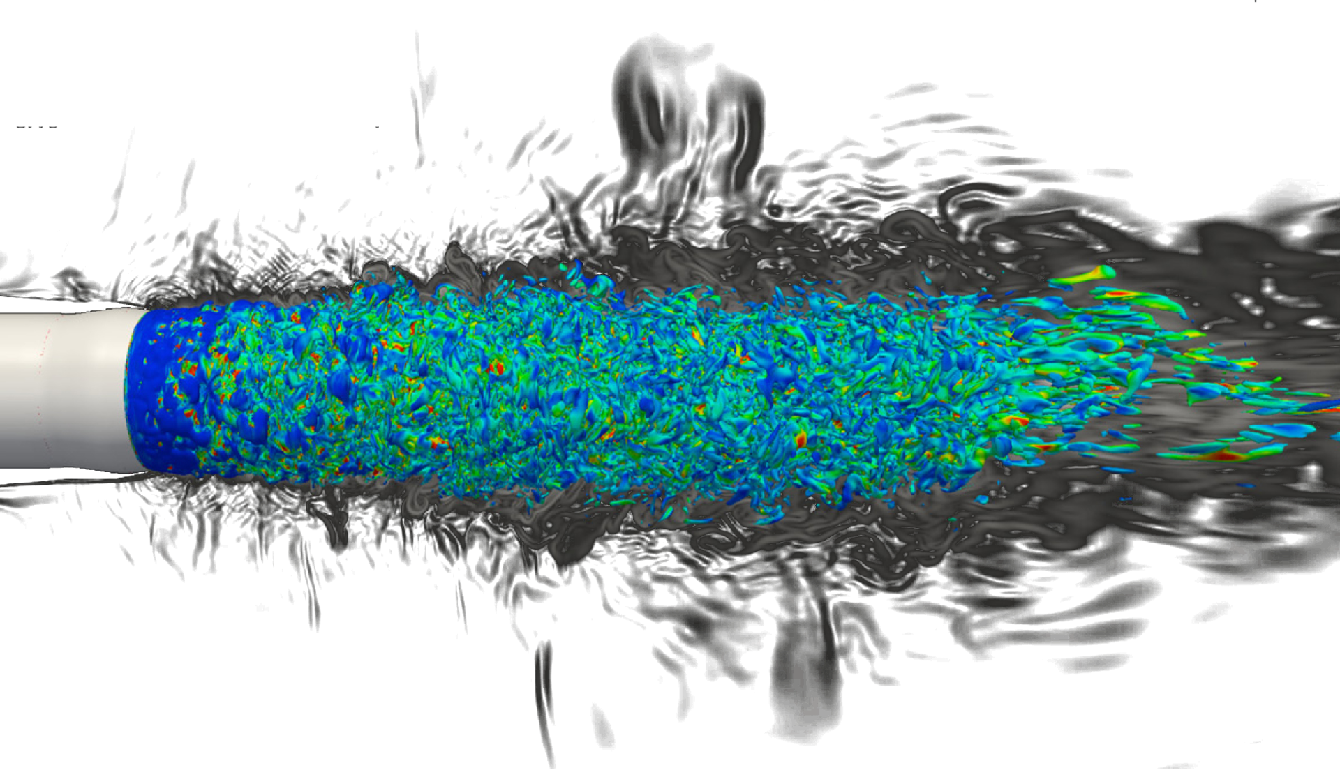
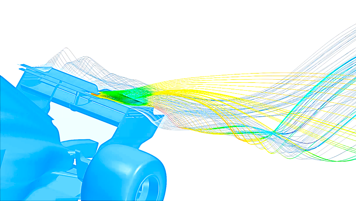
CFD solves the governing equations of fluid flow to predict how a fluid behaves and how it interacts with solid structures. Engineers apply it to aerodynamics, internal flows, heat transfer, and airflow inside HVAC systems. CFD is often paired with multiphysics simulation when fluid behavior must be solved together with thermal or structural effects. Multiphysics simulation extends this further by coupling fluid behavior with structural or thermal effects in a single run.
Multibody dynamics (MBD) simulation tools
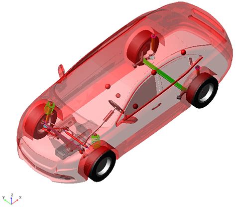
MBD does not represent full 3D deformation. Instead, it models a system as a set of interconnected rigid bodies, which is well-suited to dynamic simulations of mechanical systems such as autonomous vehicles, robots, and industrial machinery. Engineers use MBD to study how components are linked and interact within a vehicle, turbine, or engine assembly.
Discrete event simulation and system simulation
Not every simulation problem involves continuum physics. Discrete-event simulation models a system as a sequence of events over time, which suits manufacturing lines, logistics networks, and other process-driven operations rather than continuous fields such as stress or airflow. System simulation extends this logic to an entire production line, modeling how individual components and processes interact as a whole rather than in isolation.
Applications of engineering simulation
Engineering simulation supports decisions across various industries across the entire product lifecycle, from early concept work through manufacturing and field performance. The following industries illustrate how simulation is applied in practice.
Aerospace industry
Aerospace engineering uses simulation for aerodynamics, structural analysis, and thermal studies, often as multiphysics problems.
- NASTRAN remains a standard for finite element analysis.
- ANSYS, Siemens Simcenter, and OpenFOAM are also common.
- AI-driven generative design and simulation produce lighter structures, reduce material use, and accelerate innovation in aerospace programs.
Automotive engineering
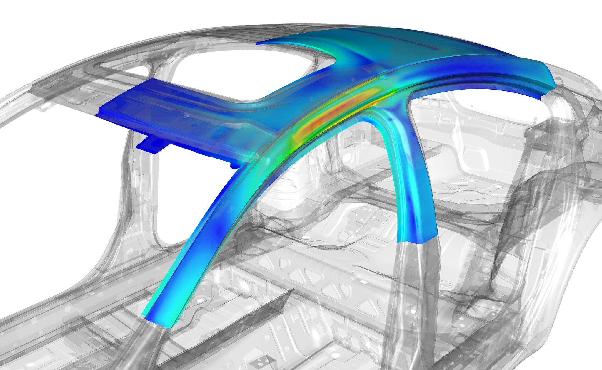
Automotive engineering uses simulation and virtual prototyping earlier than most sectors, driven by regulatory requirements and the close coordination between OEMs and Tier 1 suppliers.
- Applications span crash testing, manufacturing process simulation, and powertrain design, from internal combustion engines to battery systems.
- Thermal analysis manages heat in batteries and onboard electronics, and CFD supports regulatory compliance, energy efficiency, and the design of EV charging systems.
- In plastics programs, injection molding simulation can reduce trial injections by 25%, reducing material waste and shortening development time.
Conclusion
Engineering simulation combines mathematical models, numerical algorithms, and computing hardware to predict how a system behaves without incurring the costs of physical prototyping. As more of the design process consolidates into a single CAD environment, seamless data flow between design and simulation ceases to be a convenience and becomes a practical requirement.
Product lifecycle management platforms increasingly depend on this connection: PLM integration with simulation software supports corporate technology strategy by giving more engineers, including non-specialists, access to analyses already stored across a program.
Simulation data accumulates into a resource: hundreds or thousands of cases per project. AI models trained on this data extract insights faster than new physics-based simulations do, shortening the design cycle without sacrificing validated physics.
Key takeaways
- Engineering simulation software predicts physical behavior with mathematical models and numerical methods, reducing dependence on physical prototypes.
- Finite element analysis, computational fluid dynamics, and multibody dynamics each address different physics and require different tools.
- Simulation accuracy depends on validated boundary conditions, initial conditions, and mesh quality, not on visual output alone.
- AI models trained on simulation data cut wait times from hours to milliseconds, accelerating design iterations without replacing the underlying physics.
- Aerospace, automotive, manufacturing, and renewable energy systems companies rely on simulation to shorten development cycles and control cost.
FAQ
What is simulation-driven design and how does it optimize engineering workflows?
Simulation-driven design moves simulation earlier in the design process, so engineers evaluate structural, thermal, or fluid performance before committing to a physical prototype. Engineering simulations reduce physical testing costs by 25%, largely by catching design flaws in the virtual world rather than during physical testing. It enhances safety by simulating failures to evaluate safety margins before a part reaches production.
What are digital twins and how are they used in real-time engineering simulation?
A digital twin is a live simulation model that mirrors a physical asset throughout its operating life, updated with real sensor data rather than static assumptions. Simulation is the core of the Digital Twin in PLM, connecting design-stage models to in-service performance data. Engineers use digital twins to monitor structural integrity, anticipate maintenance needs, and test changes virtually before applying them to the physical system.
What is the best engineering simulation software for mechanical design?
No single tool covers every mechanical design problem. ANSYS Mechanical is the industry standard for Finite Element Analysis (FEA), which predicts structural integrity and stress, making it the default choice for most structural design work. Common applications include manufacturing, automotive, aerospace, energy, electronics, logistics, and healthcare, and the right tool for a given project depends on the application and the physics domain involved.
How do I choose the right simulation software for my engineering project?
Start with the physics the project requires: structural loads point to FEA, fluid flow points to CFD, and mechanism motion points to MBD. Next, weigh the learning curve and integration with the existing CAD environment against the number of engineers on the project and the timeline. If the project spans multiple sites, cloud deployment matters more than raw solver performance, since a desktop license ties the work to one machine.
How do ANSYS and COMSOL compare for multiphysics simulations?
ANSYS offers a broad portfolio of dedicated solvers built around specific physics, with deep libraries for structural, fluid, and electromagnetic problems developed over decades. COMSOL centers on a single multiphysics environment that couples different physics within a single model, which can simplify setup for problems that mix, for example, heat transfer and structural deformation. The choice generally comes down to whether a project needs the depth of ANSYS’s individual solvers or the tighter native coupling of COMSOL’s Multiphysics framework.
How does Abaqus (Simulia) compare to ANSYS for structural analysis?
Abaqus is known for strength in nonlinear structural analysis, including contact problems, large deformation, and advanced material models used in crash and impact simulation. ANSYS offers a broader range of general-purpose structural, thermal, and multiphysics problems within a single interface. Engineers handling complex nonlinear or contact-heavy problems often choose Abaqus, while broader structural and multiphysics work is commonly handled in ANSYS.
How do open-source and commercial engineering simulation tools compare?
Open-source tools such as OpenFOAM eliminate license cost and give engineers full access to the underlying solver code, which suits organizations with in-house CFD expertise and the resources to maintain and validate the software themselves. Siemens STAR-CCM+ is a multidisciplinary Computational Fluid Dynamics solution, representative of the commercial alternative: vendor support, integrated meshing and pre- and post-processing, and validated solvers ready to run without extensive in-house development. The trade-off is between licensing costs and engineering time spent on setup, validation, and maintenance.
What are the trade-offs between cloud-based and desktop simulation platforms?
Desktop simulation keeps data and compute resources on local hardware, which some companies prefer for data security or for problems small enough to run without a compute cluster. Cloud-based simulation enables collaboration among remote engineers and scales compute resources on demand, which matters for large meshes or multiple concurrent design iterations. The trade-off is between upfront hardware investment and ongoing cloud compute costs, as well as the data governance requirements each company applies to simulation results.